A month ago, a friend of mine called me to ask for help with a technical device that seemed not to work properly.
He was testing with a friend some video recording setup. They use vMix to mix (live) video streams from 4 (or more) vide cameras (Panasonic GH5 if I'm not mistaken). They also have a DataVideo ITC100 intercom system. Now the problem was: how to control tally lights via the ITC100 from vMix?
Surprisingly there are not so many affordable solutions on the market. Eventually, they found one device, made by a small US company, that would fit the needs. It's the setup of this very device that was not working properly when they called me.
TL;DR;
Go to the project's gitlab page if you want the kicad project files.
project's gitlab page: https://framagit.org/douardda/opentallylight
The non working tally light controller
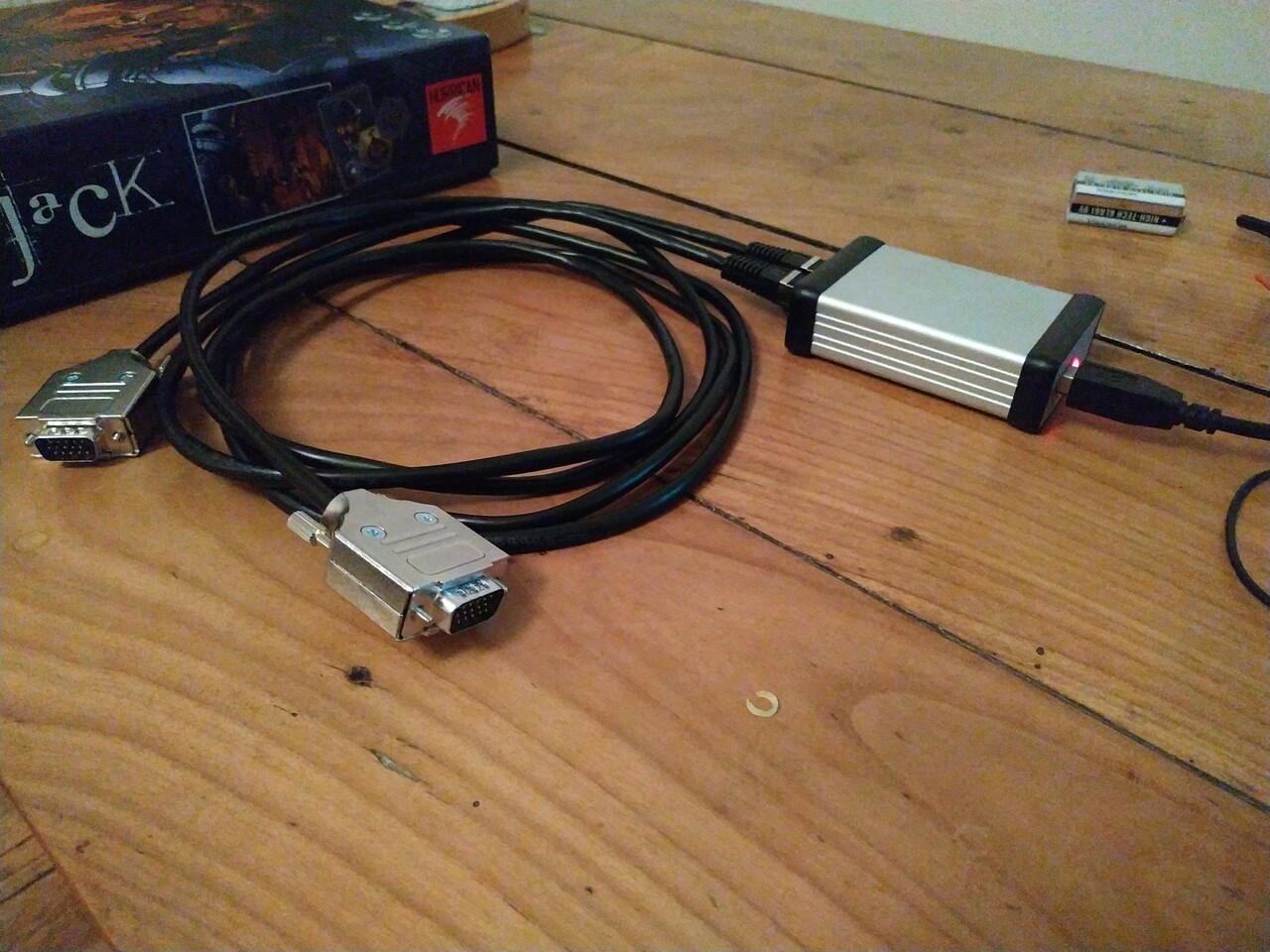
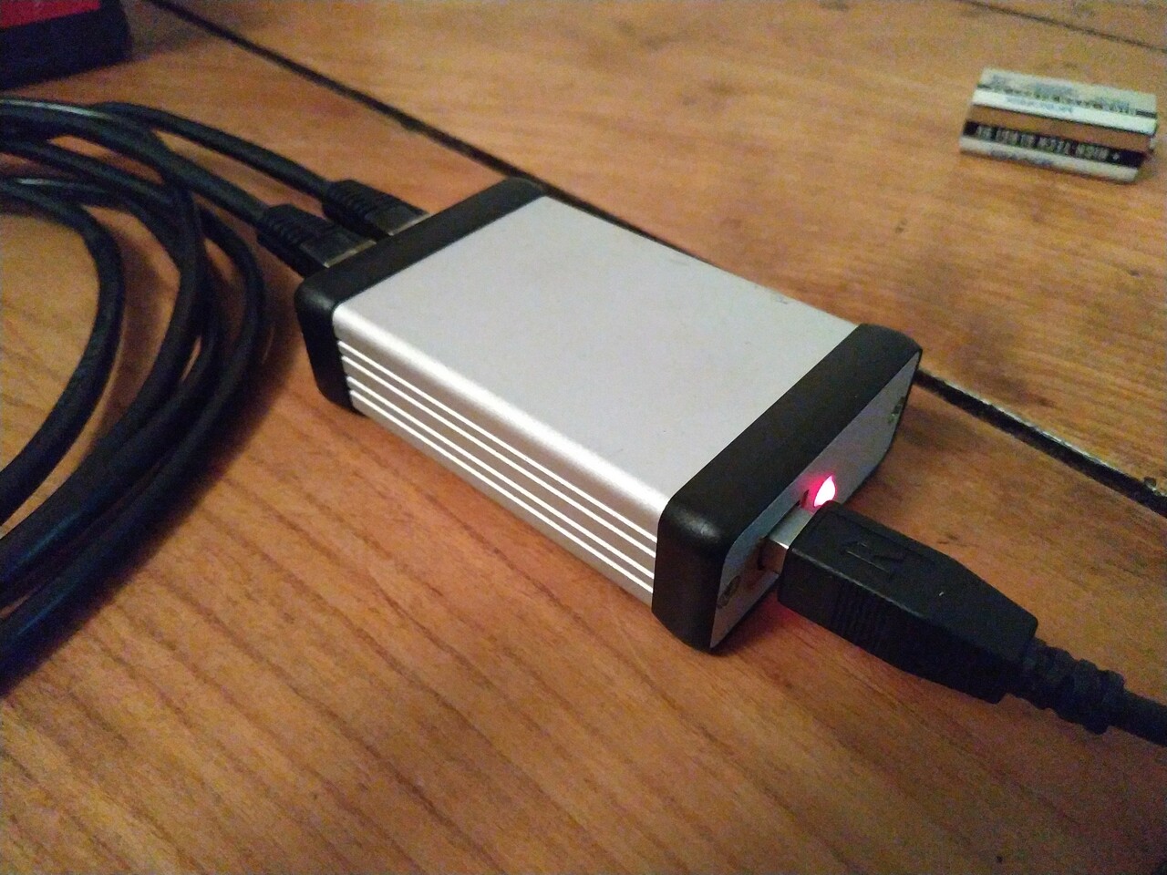
The device itself is a small-factor plastic box with a USB B connector, a LED indocator, plus a pair of HD15 connectors (for the connection with the ITC100).
The first unsual fact was the LED indicator was not on. But that not the only bizarre stuf:
- the USB device was sometimes identified by the PC, sometimes not (and no it was not a bad contact),
- when plugged to the ITC100, some tally lights immediately lighed up but quite dimly,
- and no attempt to change the current and preview streams did not change anything on the tally light side.
So I grabbed the device home, opened it up and tried to identify a possible problem. At that time, we knew the PCB had a problem (because of the LED staying off), and the seller sent a new PCB (without the case to save a bit on the shipment), so I was not too worried of hacking the dead PCB.
I discovered a short circuit between the pads of the LED, and this was disturbing the 5V USB supply. In fact, depending on the hability for the USB ports used on the PC to deliver enought current to actually power the microcontroller or not, the device was seen by the PC or not.
I though this was the problem, so I just removed the LED and it's limiting current resistor: no more over current on the 5V rail, the device was now properly recongnized by the PC every time weplugged it in.
I also tried to understand a bit the circuit which was in fact dead simple: a PIC18F4553 microcontroller is presented as a HID device to the PC and control directly (via a resistor) the pins of the HD15 connectors.
So I tried to 'reverse engineer' the "control" protocol and since it was a simple HID device, I just wrote a small Python script to try all the possible addresses on the first 2 bytes, using pyhidapi. And I quickly discovered how to control individual pins connected controlling the tally lights (via the ITC100). On my Linux machine with a simple LED connected directed to the HD15 connector, it was looking like it was working.
But once plugged on the ITC100, it was still not working. Same erratic behavior, same total absence of actual control of the tally lights.
This time I had a multimeter with me, so I took measurments on the ITC100 side: each tally light signal was at 12V! and had to be pulled down to ground to light the corresponding tally light on.
Since the device was attempting to control directly these signals from the PIC, no way this could have ever worked. And this was sold something like 650US$ plus shipment...
A first prototype
So I explained to my friends there was no possible way of making this device work as intended: it was just not designed correctly. Meanwhile, one of them told me that vMix also have support for controlling tally light via Arduino-based setups using the Firmata protocol.
Since the fiasco with the "professional" device they bouight, they were really on the urgent need for a working solution, like for the day after, so I spent the evening building a very rough prototype.
I wanted to provide them a better solution, besides a working one. Like with proper galvanic isolation between the microcontroller and the ITC100 part of the circuit.
Since I had no time nor enough optocouplers in my stash of junk parts, so I just used regular non isolated 2N2222 to control the ITC100 tally light lines.
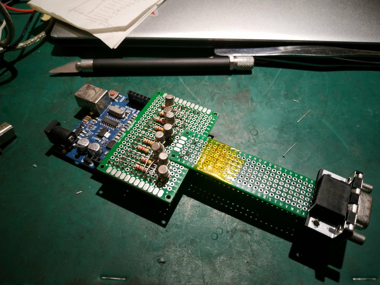
It's a very crude protoype, but i worked! Believe it or not, but they have been able to record several events with this board!
A (slightly) better protoype
Since we validated the Arduino and Firmata based approach, I proposed them to design and build a better device.
At first, I kept the idea of using an existion arduino compatible board and only design a daughter board for the optocouplers and the connectors.
I chose the Sparkfun Pro Micro: it was one of the smallest board with enough pins to drive the 8 tally lights (each with 2 LEDs, the green for preview signaling, and the red for signaling the recording in progress).
So I designed a first PCB (in fact several of them, but meh) using Kicad.
In the mean time, I also spent quite some time looking for a nice aluminium enclosure for the PCB. I finally found a small extruded one for a 80x50mm PCB on aliexpress. It was perfect, so I ordered 5 of them.
I also decided to replace the HD15 connectors by RJ45 ones, then assemblng custom cables from shielded RJ4 Cat6 ones.
So I ended up with this design:
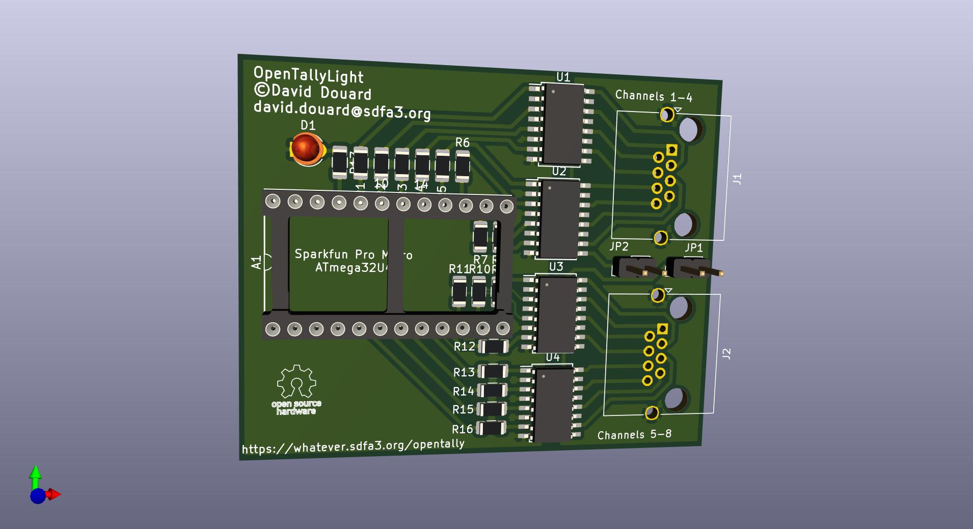
Looks neat, but... I did not realize I put the RJ45 socket backwards! Doh!
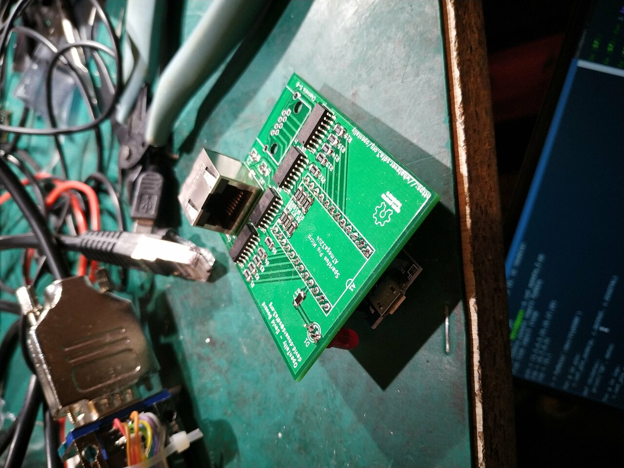
In order to test is nometheless, I put the Pro Micro on the back side of the PCB (otherwise I was not able to plug the RJ45 cable in).
Unfortunately, if this board worked fine on Linux (I mean the Firmata protocol part, since vMix does not work on Linux), the Firmata protocol on Pro Micro is not working on Windows. vMix was not able to establish the connection with the Pro Micro, neither did the Firmata test program available on the Firmata web site. I'm not sure why it did not work on Windows, but I had no time nor the desire to debug this Windows evil misbehavior.
I looked in my tray of development boards, and found a few Nucleo ones that are supported by the Arduino environment and have almost compatible pinout with the Pro Micro. I had to budge a pair of tracks on the PCB, but I could make it work.
OpenTallyLight
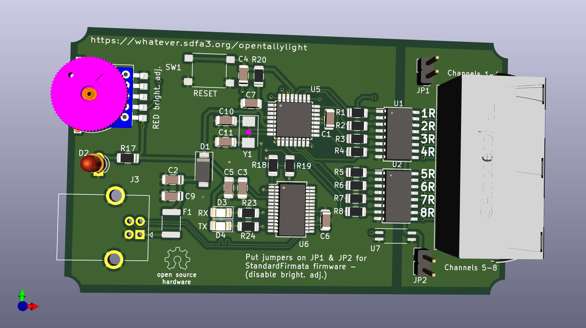
So I designed a new version of the board. This time I stick to a good known working pair: an ATmega328P + FT232RL based solution (the Pro Micro is based on the ATmega32U4 which embeds the USB controller).
I wanted to use a USB B connector rather than a micro USB one (too fragile for this kind of environment), and since I also wanted the design to stay small enough to fit in my cute little enclosures, I decided to implement the arduino on the PCB itself.
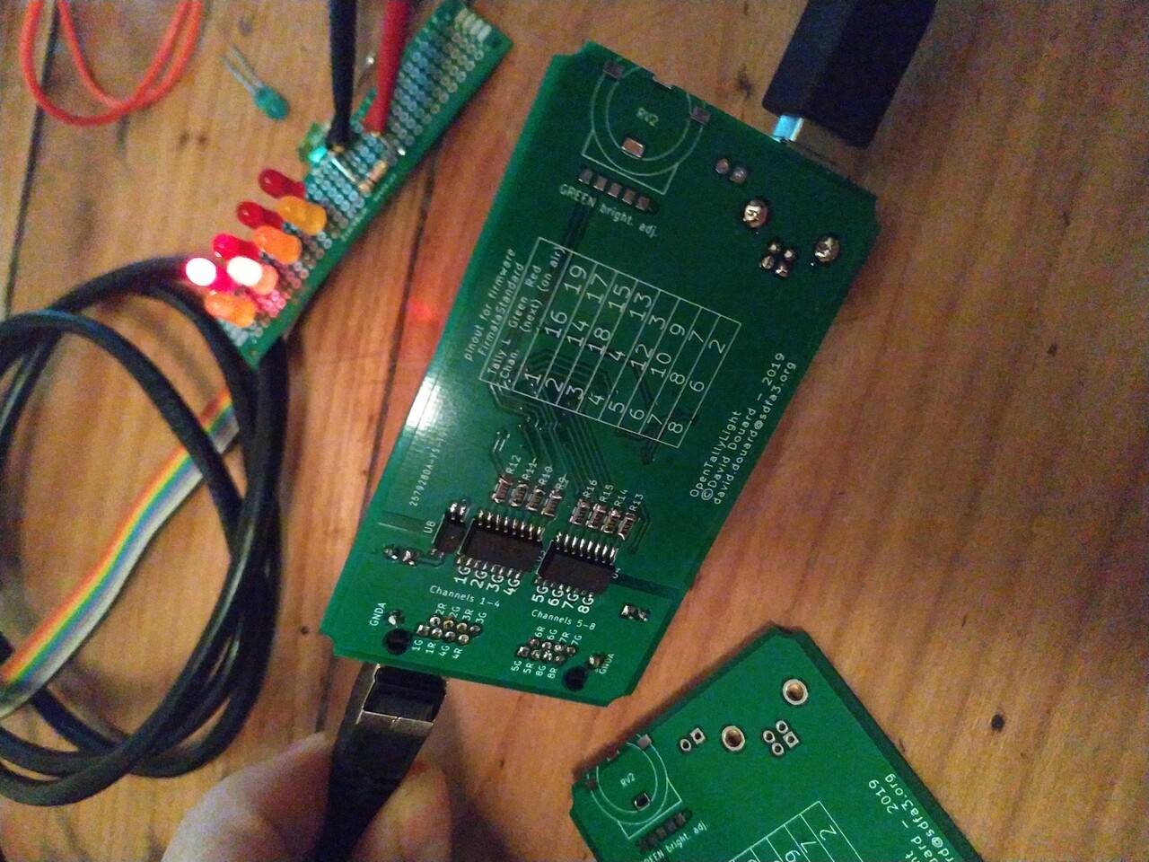
The PCB design looks like:
Which gives, in real life:
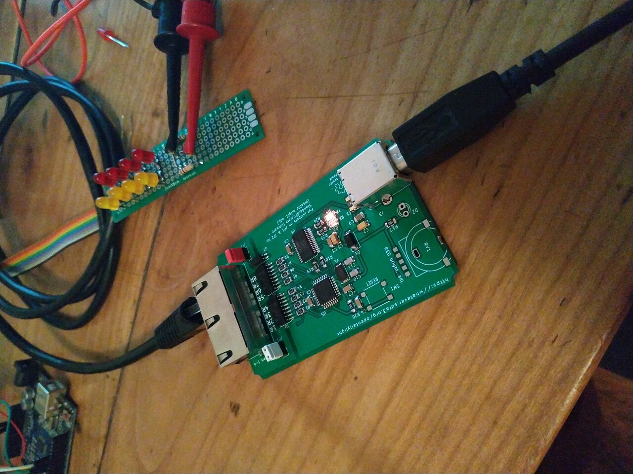
And the result once installed in the enclosure:

The good news is it worked immediately. The bad news is I forgot to put an ICSP connector on this PCB. So I had to burn an Arduino bootloader on the ATmega chip before I soldered it on the PCB.