A had a non-working Dell 2407WFP LCD Monitor in my stash for quite a long time. I recently decided to see if I can fix it. It is a quite old but pretty nice 24" LCD monitor, with a 1920x1200 resolution.
The symptom was the nice kind: dead. No light, no LED, no power consumption.
Presentation
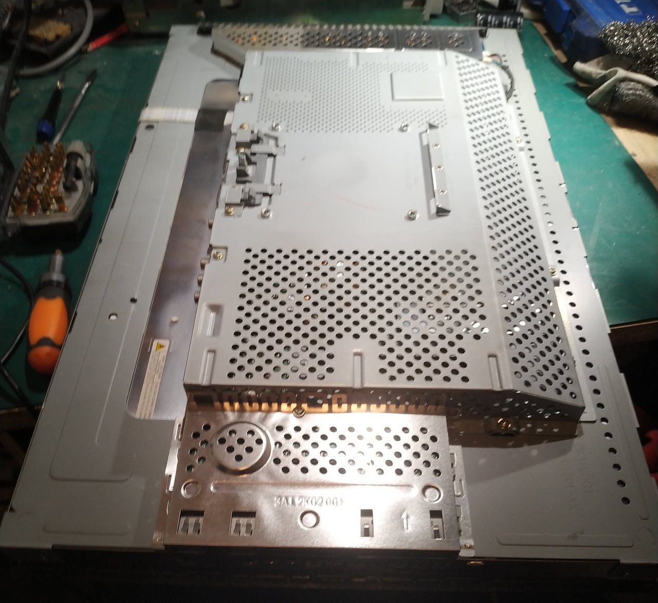
The enclosure is reasonably easy to disassemble: 4 screws on the back, then the usual plastic clips to unclipse all around the enclose. The result is a very standard view for these LCD monitors: a big metallic enclosure:
When removed, the also very classic view on the boards:
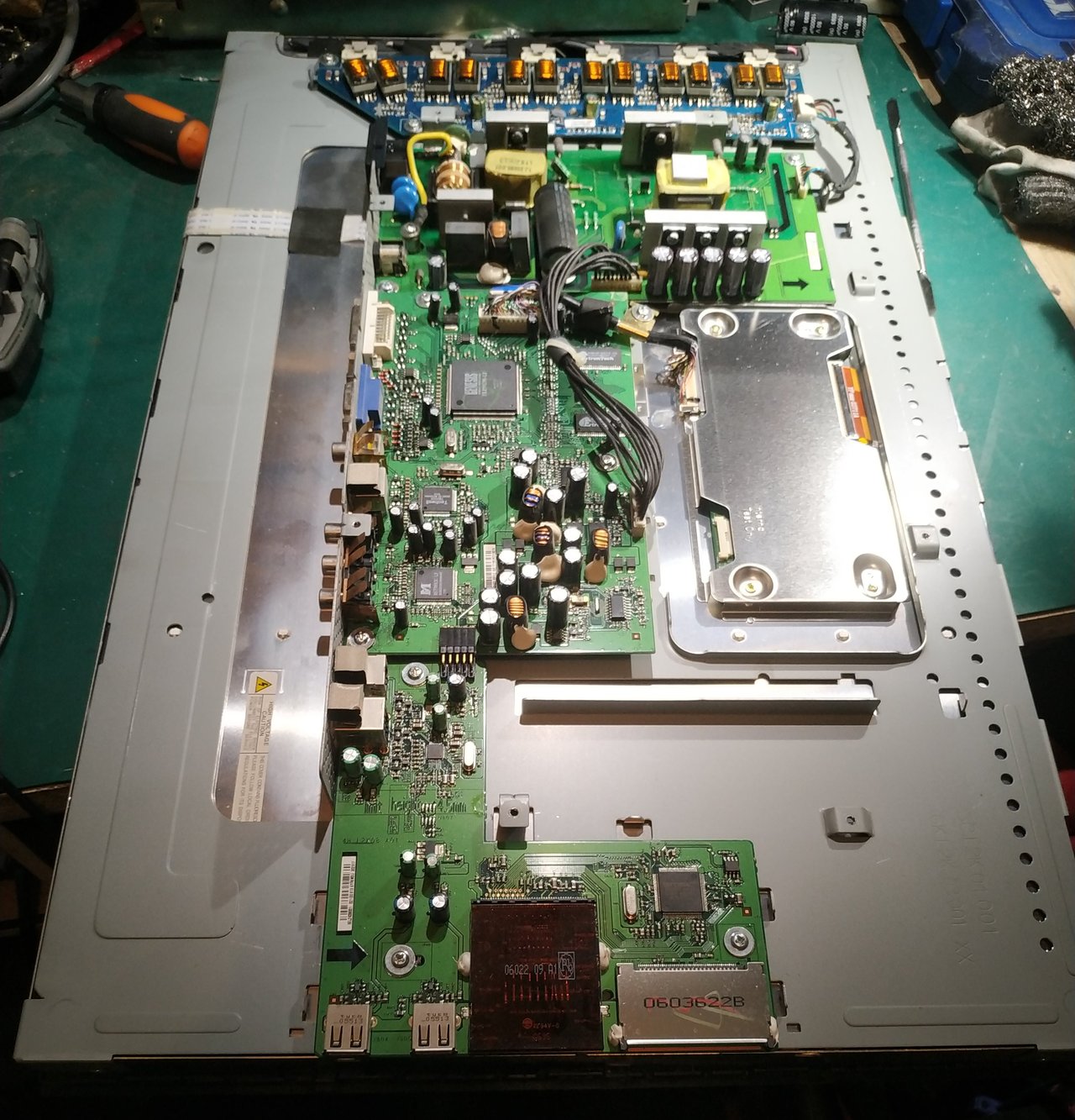
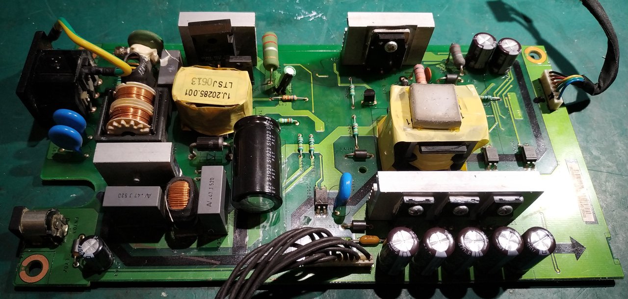
Since there is nothing at all, the first and most probable place to start looking is the PSU:
Diagnostic
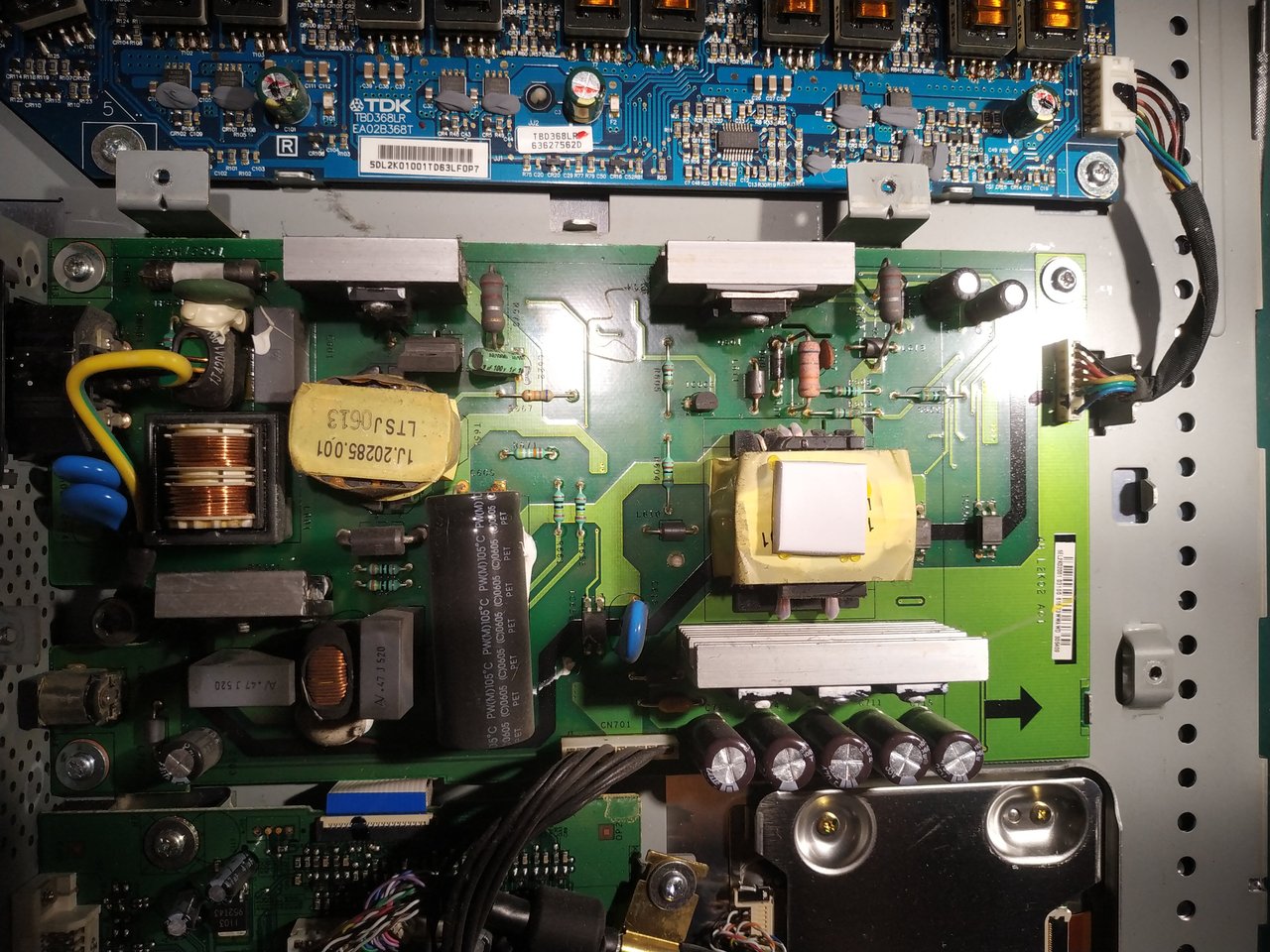
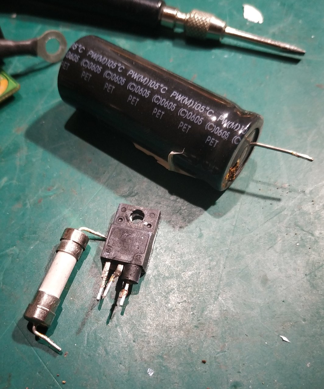
Inspecting the PSU, the first culprit (and the probable origin of the failure) is pretty obvious:
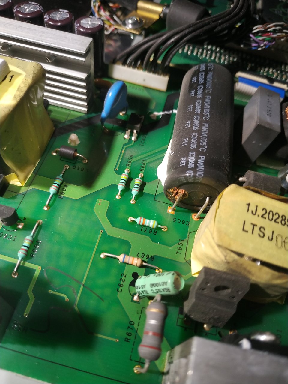
This one is dead, right, but the question is if it died alone (very unlikely) or if it took a series of other parts with it.
Using the multimeter in diode mode, I immediately found a dead fuse (good sign, might have done its job and protect some other parts on the PSU... or not), but also a dead MOSFET (Q651, the one on the PFC stage) and maybe more:
At this point, finding datasheets for the controller chips on this board looked like a good idea. Most of the time, these PSU designs are very close to the application circuit described in the datasheets.
The schematic
There 2 controller chips on this PSU, the classic pair with a primary PFC controller (L6561D) in charge of providing a nice B+ DC rail for the PWM controller (NCP1200A) driving the main transformer.
I could easily find datasheets for these 2 chips. But the nice thing when fixing such a mass produced device is that obviously some other people already had a similar failure to fix.
It seems that the problem my monitor suffered is a very common one. I found a long thread (obviously on https://www.badcaps.net) where people discuss this flaw and their quest for fixes. Which led me to a PDF with the full schematic of the PSU (which is in fact a BenQ brand).
The first stage of the PSU, around the L6561D controller looks like:
And the regulation stage:
For the record, here are the typical application schematics from datasheets:
As you can see, it is very similar to the first page of the schematic above. This later has the extra power button management circuit, and a few details and component values are different, but overall, a very close application of the typical application schematic (as expected).
And for the PMW stage, I could not find such a typical application circuit more advanced than this very basic one (from the datasheet):
However some interesting details and circuit improvements can be found in this application note.
Dead parts
Having Q651 dead, I started looking for other victims of the deadly C605 electrolytic capacitor. I quickly found a few more parts, especially R670 (0.22R 3W). From there, I bought a bunch of parts, obviously the one already mentioned plus a few more references that were listed by a few people on the thread list on badcaps (15v zener diodes, 4148 (SMD), and PMBT2907 (PNP) transistor for Q602). I also ordered a few replacement parts for IC601 and IC651 since they had also probably suffered from the failure.
I first replaced the obviously failed components (Q651, C605, R670 and the fuse). I probed all the transistors and diodes I could. Even the controler chips did not seem obviously wrong (no short legs).
I applied gradually power (via an autotransformer) watching at power consumption. Nothing wrong, no magic smoke. And even 19v on the output rail!
More dead parts
So I attached a bunch of power resistors to the 19V output rail, which made the PCB rapidly start to smell and smoke.
Something was wrong, not catastrophic (no big explosion nor massive smoke, but still).
I finally found the smoke was generated by... the earth wire which was touching the input NTC! This later was getting very hot.
So, it looks like it worked fine as long as I did not load the output. Interesting. From there, the MOSFET transistor driving the PFC stage (Q651) was dead again.
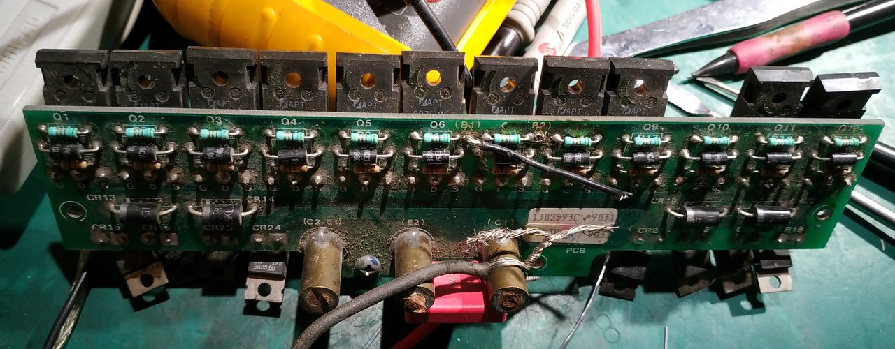
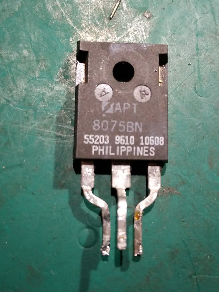
So I decided to replace IC651 (the PFC controller, L6561D). And since I had not that much spare STP10NK60ZFP transistor for Q651, I decided to try first with some junk parts from a PCB laying around, on which are many APT8075BN:
The leads are not exactly the same spacing, but I managed to do something:
Which resulted in a rather acrobatic setup: I did not want to fight to make it fit nicely enough that I can screw it on the heatsink (plus it is not insulated, like the original transistor, so I would have had to find an insulator. I have some, but finding them would have required a bit of digging in my overcrowded empire of dirt).
The resulting setup looks like:
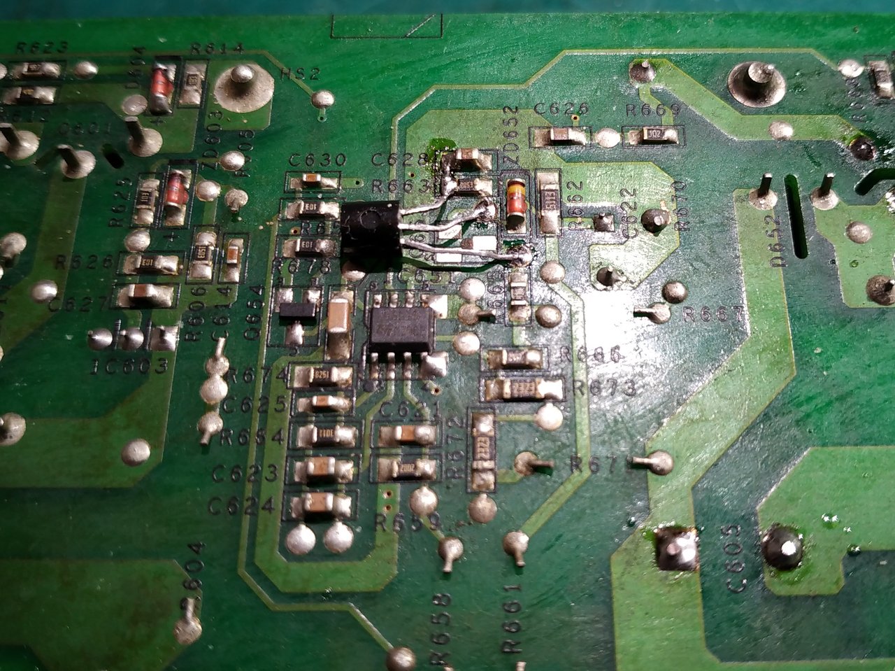
However, before applying power again, I checked all the silicon components once more. And I discovered (what I missed the first time) that Q653 was also dead.
The problem was I had no proper SOT23 replacement part for it. The good news is I do have a few 2N7000 that can be used, but are TO92 packages. So I did a bit of surgery:
Fixed
Applying power again, the 19V is back when no load is applied to the 19V rail. And stays alive when I draw current (1A).
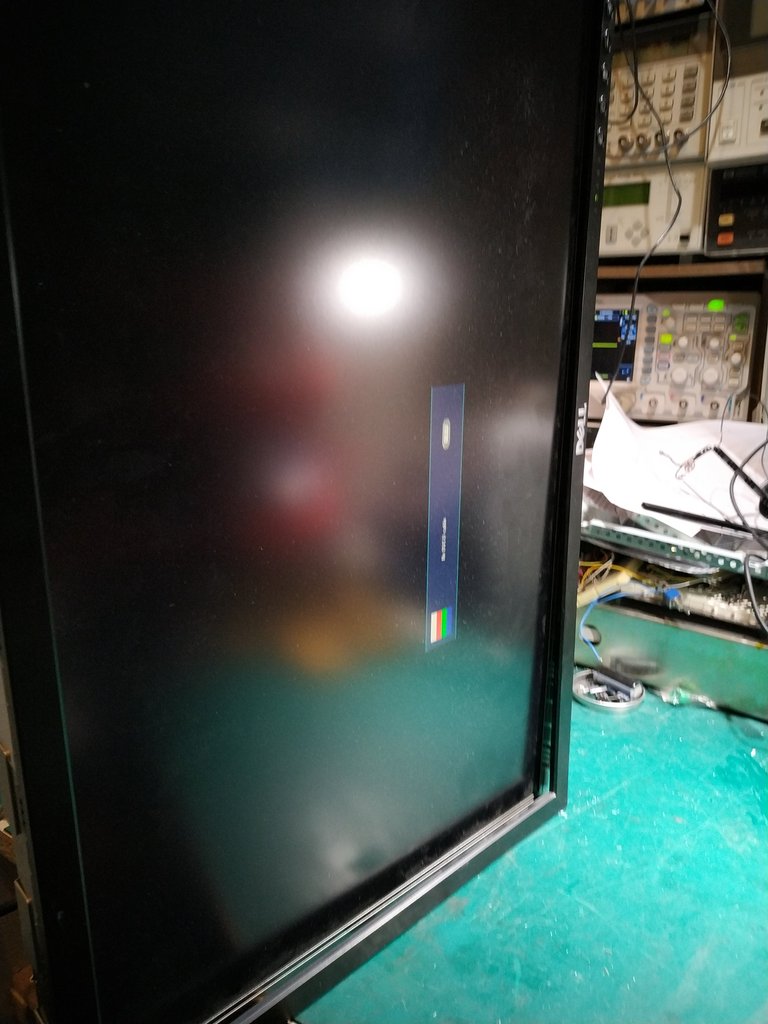
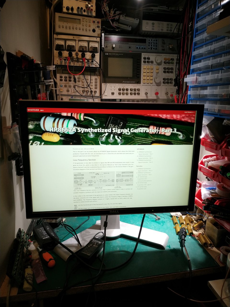
I plugged it back in the monitor, the green LED lit as well as the display itself showing the 'No signal detected' message box!
I replaced the temporary Q651 transistor with the proper reference, checked the result, then put everything back together.
However, before closing the box, I did a few tests and measurements, for fun. I found the reason for the properly working 19v rail when unloaded at the beginning: in fact, the L6561D PFC chip is only turned on when some load is detected by the NCP1200A controller. This allows the standby power consumption of the monitor to be very low. I believe this is done via the Vcc1 signal that goes from the second stage (PWM controller) to the power on circuitry on the PCF stage (Q654, R678, R656 and the transisor part of the IC652 optocoupler), which only applies power to IC651 (the L6561D PFC controller) when needed.
A nice monitor. Definitly not for my desk ;-)