A friend of mine had a problem with his (a bit old) 24" HP monitor: the device was working properly, but only for a while (few minutes at most).
Looked like a good candidate for a quick repair, problem being most probably bad caps are so.
The first step was to find out how to disassemble the down thing, since these "modern" things are not designed to be serviced and have no screw, only plastic clips which are so easy to break.
Whatever, I finally succeded in opening the box (with only one or 2 broken clips).
Overview
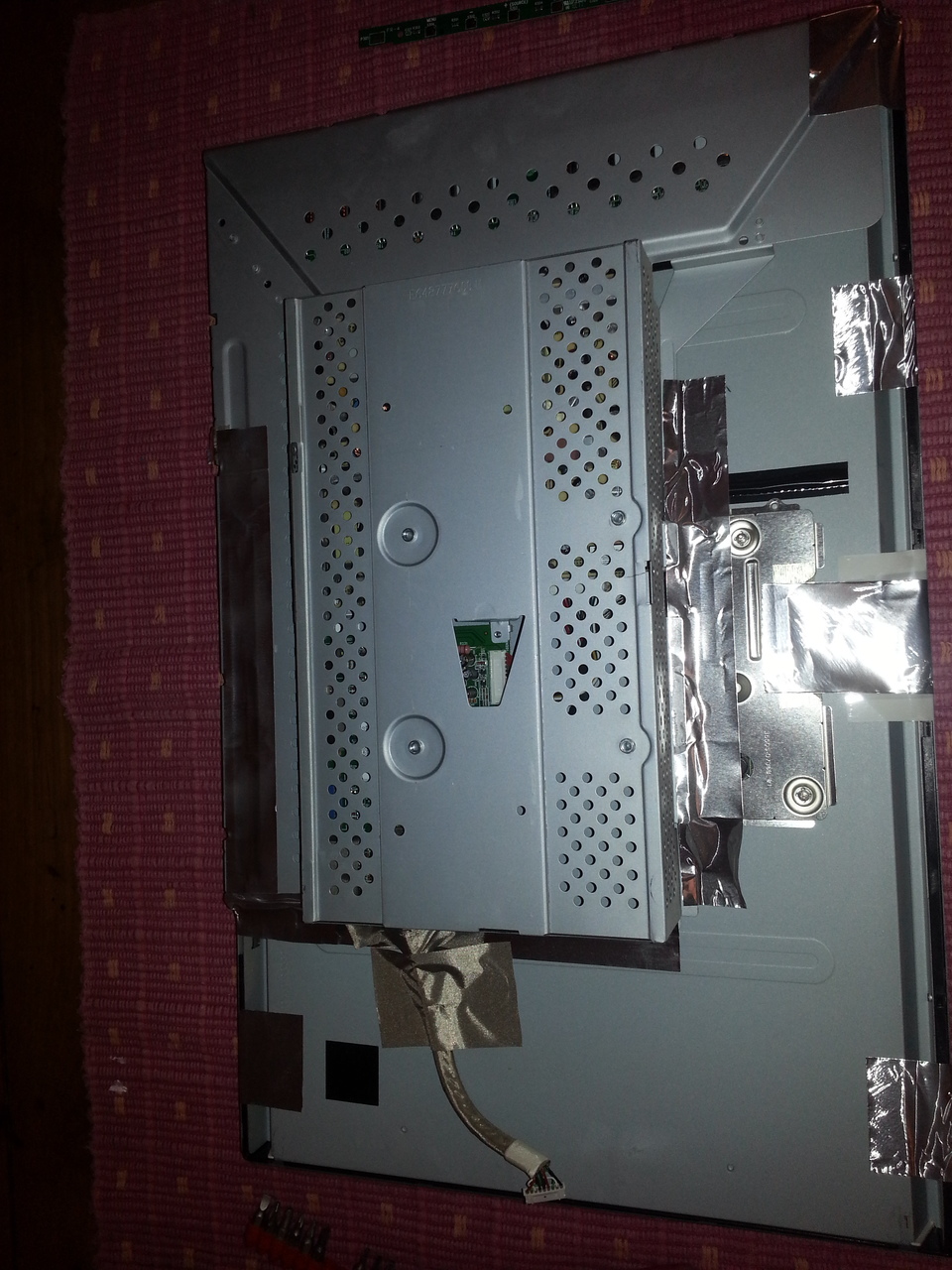
Inside the beast, the usual stuff under the shields:
- a PSU,
- a main controller board,
- an LCD driver board, and the monitor being a bit old,
- a blacklight HV driver board.
First thing, to make sure the problem comes from the PSU, I powered the monitor from my bench power supplies. I used one output of my HP E3648A to generate the 19V rail that powers the backlight. It was a bit short (CC limited at 16V), but enough to power the backlight. The second output was used to produce the 12V, and the 5V was generated by my very old home made PSU.
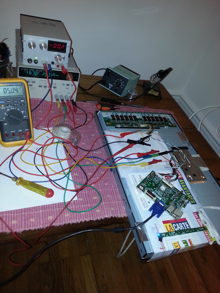
The monitor was working fine when powered from these PSUs, so the problem was, indeed, this Tatung PWB-1336-02 switching PSU:
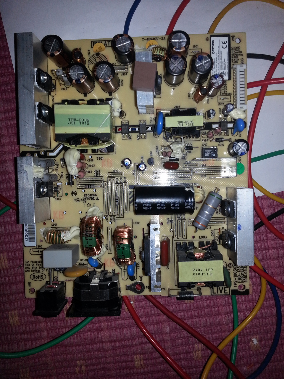
The design is nice and clean. Electrolytic caps however are not the best ones (mostly Lelong ones I think), which is not really a surprise in this kind of device.
At first sight, nothing strike the eye, no leaky cap, no burnt resistor or PCB...
Not a 10mn fix, in the end.
The PSU generates 3 voltages:
- 5V @2.7A
- 12V @0.8A
- 19V @3.2A
Finding the problematic power rail
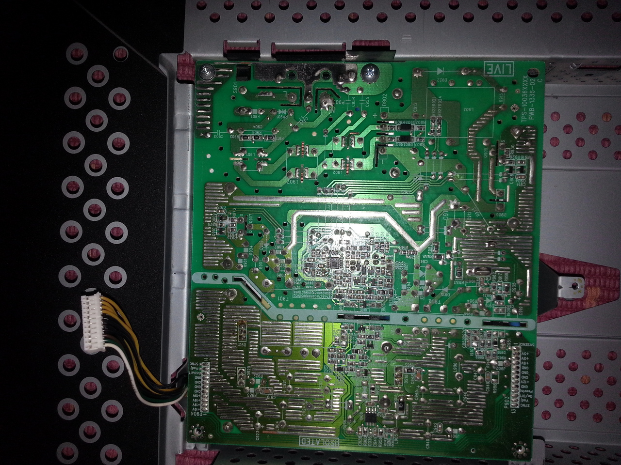
There is a hard switch on the PSU, next to the IEC socket, and When the power is on, the 5V is hot, wether the monitor is on or in standby.
When the display is powered on, the 2 other voltages are started.
The pin 10 on the cable between the PSU and the main CPU board is dedicated to the "power saving" state. It must be high (at 5V, which is always present) to enable the 2 other voltages.
Note that there are 2 other pins dedicated to power management (pin 11 and 12, marked as "On/Off" and "Vadj"). But these are directly routed to the backlight board and take no part in the PSU management.
My first test has been to plug my cheap electronic load on the 5V with the 2 other voltages stopped.
And I could reliably sink 3A from there. So the problem must be on one of the 2 other rails.
But I also could sink the max amperage from the 2 other power rails (1A from the 12V and 3.5A from the 19V)...
Ok, so each power rail seems to work fine alone.
But when I sink current from the 5V rail while the 2 other voltages are up, then the PSU fails after a short while.
I've tried to probe a bit the switching curves using my Rigol DS1054, but the PSU being "hot" (around 400V), and having no isolation transformer, I could not probe the signals correctly (using 2 probe and displaying the A-B curve, which is some kind of a joke on the Rigol, since you cannot hide the A and B curves: the curve substraction is purely computed from displayed curve. When I found how useless this was on the Rigol, I had not enough energy to extract my old Tek 2445A from under the pile of test equipment stowed in the closet...)
A glimpse at schematics
At this point, I needed to try to understand a bit the schematic. I wasn't even sure the problem came from this side of the PSU, it could also be a problem in the "isolated" part (bad caps, bad optocoupler, bad voltage reference...). I had checked the main caps, and they seemed to be ok (not quality japanese brands, but still the correct value and low ESR).
On the live part, before the transformers, there are 2 chips :
The 12V is produced from the 19V rail by a small DC to DC converter (FP6185).
In fact, this PSU design is almost just the 2 application circuits (found in their respective datasheets) merged together.
The noticable points are:
The TNY279PN DC input can be come from either the input bridge rectifiers (via a diode and a thermistor), or, when powered, by the DC produced by the CM6807 via the PFC circuit. So when the CM6807 is down (when the monitor is in standby), the DC input for the TNY279 is around 318V, but when the monitor is on, the CM6807's PFC circuit rise this voltage to almost 400V.
The bias winding, normally used to power the TNY279 (to allow a very low no-load power consumption, datasheet says <50mw) also powers the CM6807.
A funny side effect of this design is that the CM6807 cannot be started if there is no load on the 5V rail: in this case, the auxiliary voltage of the transformer managed by the TNY279 is not enough to start the CM6807.
The application circuits are as follow:
In this PSU, the input DC of the TNY279 (the point just before R5 in the app circuit) in connected just behind the PFC circuit, i.e. just after the D2 diode of the CM6807 app circuit.
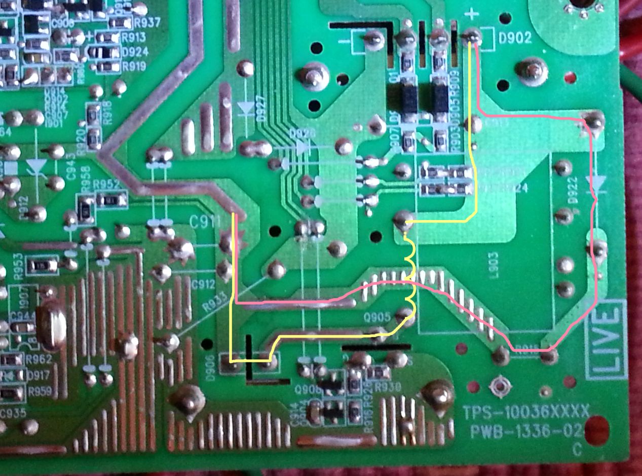
In order for the PSU to generate the 5V rails even when the CM6807 is off, there is derivated DC input path, from the bridge rectifier to the input DC rail, consisting in a diode (D922 on the PCB) followed by a thermistor (R915):
Finally, the culprit
While testing the PSU powering the CM6807 from an external source, I notices another strange behaviour: the TNY279 enters a failure as soon as I sink current from the 5V rail, but it remains faulty as long as I let the CM6807, thus the PFC running, and the input DC at 400V (instead of 318V when the PFC is not activated)..
At this point, I though there is not way the problem can come from the 5V regulation loop, neither from the CM6807 circuit, so the only culprit left would be either the TNY279PN or a component close to it, a cap (especially the BP/M one), a diode or a resistor. So I tested these parts (again, to be fair), and I replaced the cap connected to the BP/M pin. With no improvement, the only remaining faulty part must be the TNY279PN.
So I decided to buy a couple of them from RS, and 2 days later I replaced it, which did fix the PSU.
What a tricky half-failing part!