Many electronics test equipment need an accurate time base. Most often, it's build on a 10MHz base.
For quite a while now, I have a used rubidium frequency and time reference (Efratom Model LPRO-101) waiting for a nice enclosure. I also have a small Extron Electronics video signal amplifier I thought I could use to make my freq reference able to provide its signal to several test equipments at once.
The Rubidium Frequency Reference
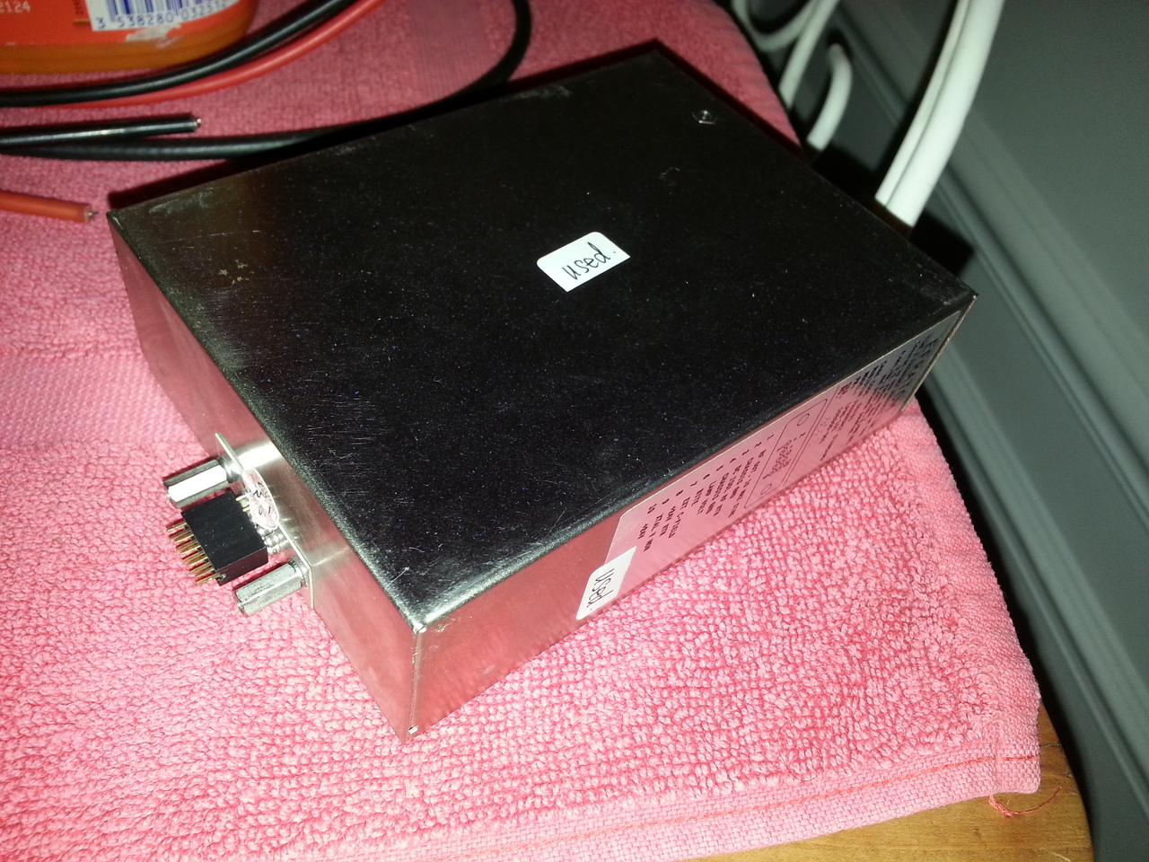
The device is a small enclosure with only a 2x5 pins connector:
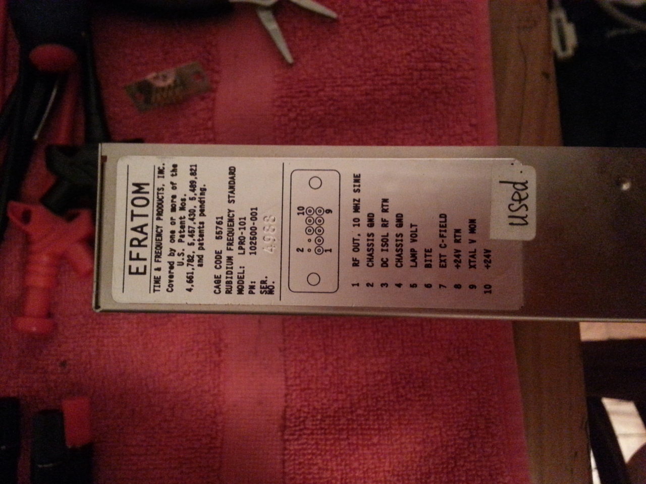
The exact model is an Efratom Rubidium Frequency Standard Model LPRO-101:
Inside the enclosure, there is a single PCB with SMD and through hole components. It's quite dense.
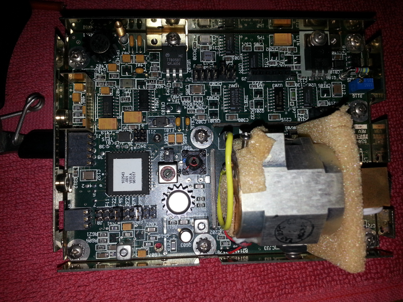
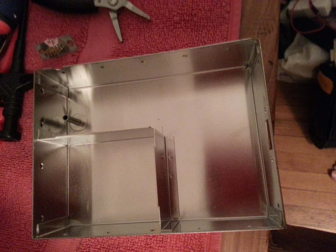
The rubidium lamp with the resonant cavity occupy almost a quarter of the total area. The cover of the enclosure is compartimented, mainly to shield the lamp+cavity device from the remaining of the board:
The Rubidium Freq Ref seems to workjust fine. I've powered it a few times, and it take a few minutes to lock the lamp and stabilize the output frequency. I've made a quick measurement of the power consumption; at startup time, the current goes up to 1.5A, but after a while, it stabilize around 0.5 or 0.6A. According a voltage 24VDC, it starts with 36W then goes down to 15 or 16W.
Now, I have to embed it in a nice enclosure (preferably an aluminium one so I can use is as a heatsink, since the frequency reference produces a bit of heat.)
The Extron Video Amplifier
The video amplifer on the other hand has a bit of a trouble:
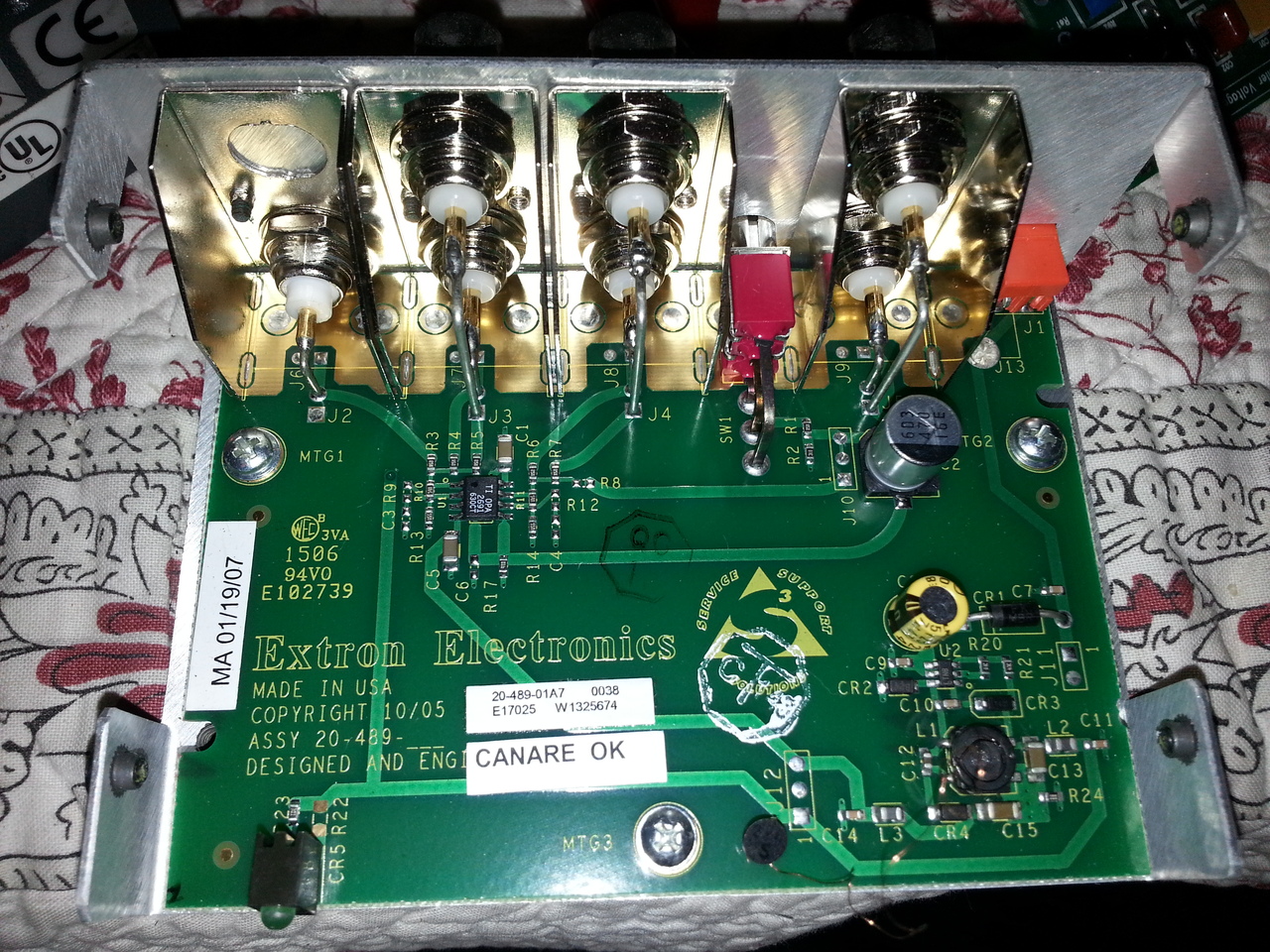
As you can see on the picture above, the inductor is broken, and there is no visible mark on it. This inductor is used to produce the symetric voltages required to poser the opamp used to dispatch the signal.
The switching power modules used on the board is a LT1616 (marked as LTNB on the S6 package). So I reversed engineered a bit the schematic of the power to try to guess what kind of value this double inductor could be, since the reference schematic in the datasheet does not use such a dual inductor(/transformer).
Fro the schematic I could extract, it appeared that the design is in fact very close to the reference schematic proposed by LT in the datasheet, in the Bipolar Output DC/DC Converter configuration page 16:
It produces +/-5V from the 12V input. But still, I did not know what kind of inductor/xformer I should use. I did not notice at first sight the two references for the inductor that are proposed in the reference design. So I first searched using the nice faceted search tool of digikey (reducing the selection according the informations I have on the broken device and then looking at the pictures), I finally could find the reference of the inductor. By the way, it's a Sumida CLS62 Series inductor (as indicated in the datasheet). And according to the reference design, it should be a 22µH one. So let's make a purchase for this inductor as well as some 20k resistors for my HP8904A.