What Is This About
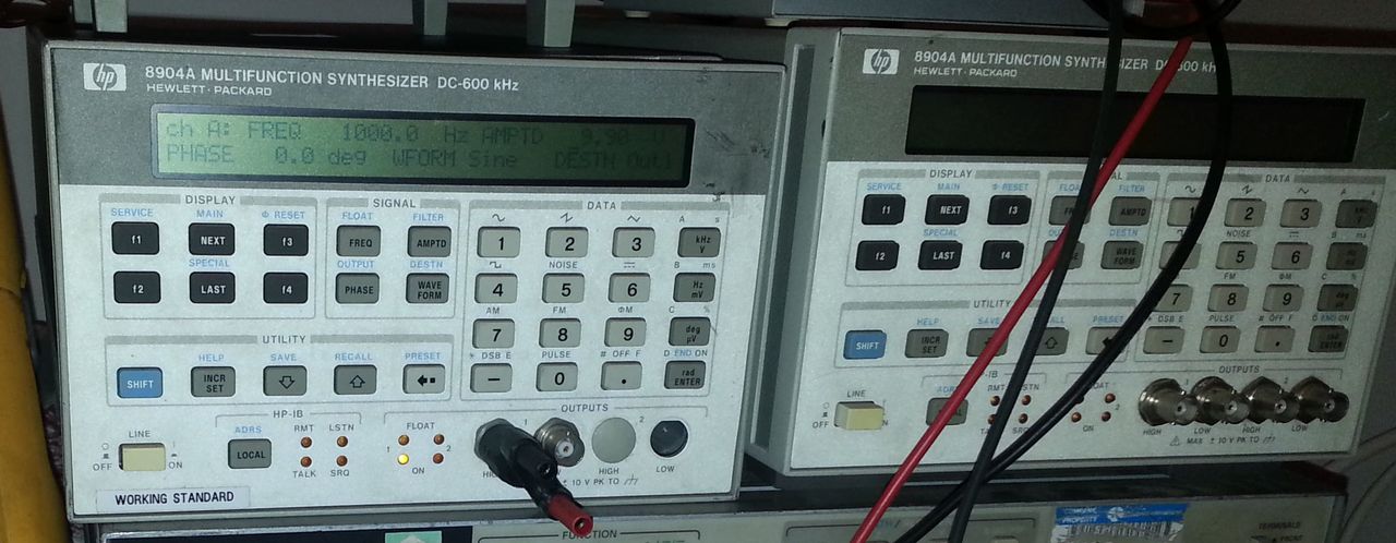
I have a couple of HP8904A multifunction synthetizers for years (bought them on ebay around 2007 IIRC). One of them is working properly, but the second one had very inaccurate output levels, generating a non-symmetric signal when output level was set above 5V or something like that.
I knew for a fact that the PSU was the problem (thanks to the fact I have 2 units, I could easily swap elements between the units). Back then, I spent a bit of time trying to figure out what was going wrong, and detected the +16.3V output of the PSU was failing at around 9 or 10V. I did not had a chance to investigate more then.
For some strange reasons, I've recently decided to fix this PSU problem.
The PSU Problem
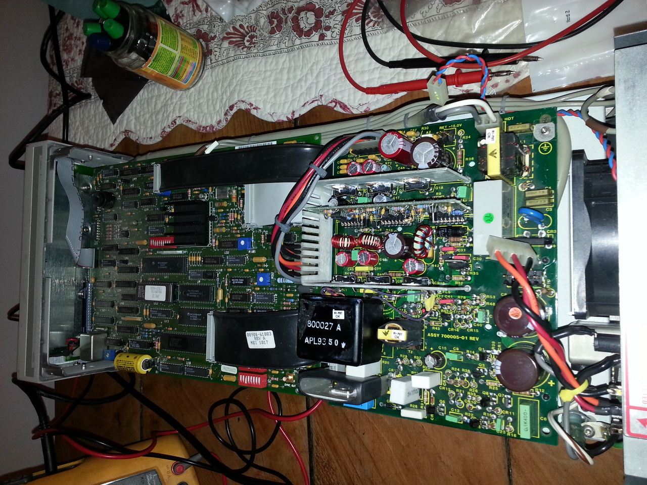
The PSU board is the one at the rear of the unit, on the upper part of the case (the lower part hold the analogic boards). The PSU is not a custom HP board, but is a Computer Products switchmode supply (90 Watts, Model XL51-5601).
It delivers 4 voltages on 2 separated ground planes:
- a +16.3V and -16.3V rail (with their own ground plane),
- a 5.1V for logic devices,
- a -15V (same ground as the +5.1V) which powers at least the fan.
There are not too much material on the web about the possible PSU problems of this equipment. A few threads on forums and this very interesting blog by Simon Schrödle
But his problem was different from mine.
On my device, the problem was with the +16.3V output falling at around 9V on load. The level was at his proper 16.3V level when the main board as not plugged in.
I first gave a close look at the caps, looking for some evidence of a failing capacitor... which is always the culprit to think of in this kind of situation. But I could not find anything obvious.
So I started to reverse engineer the circuit to try to understand a bit the possible causes.
The PSU consists in 2 PCBs, the main one which is a double-layer PCB, and a small daughter board with several op amps and zener regulators. Obviously the regulation stuff.
In order to be able to follow the tracks, I had to remove the heat sink and split these two boards apart, since it's not easy to deal with this:
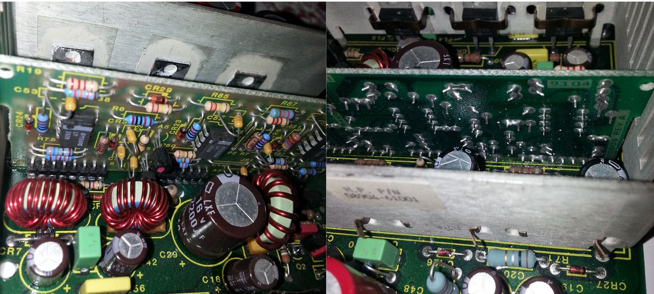
So I removed the heatsink and disassembled this small board from the main one (which was quite painful, since I don't have a disoldering station. Disassembling the 3x 8 pins angle connectors from the double sided PCB was not a piece of cake...)
After that, I noticed a possible leak of a small cap, but this was on the 5.1V rail. Should not be related to my +16.3V problem.
But I decided to take advantage of having disassembled the PSU to replace a few of these caps, starting with this dubious one.
I also decided to replace the soldered assembly for the two PCBs by some connectors so I can easily install and remove the daughter board.
After having replaced the caps, the PSU was still failing. So I really had to understand the schematic to investigate more.
The part of the schematic involved in the +16.3V rail is the following:
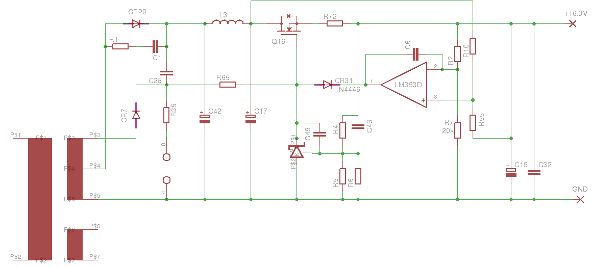
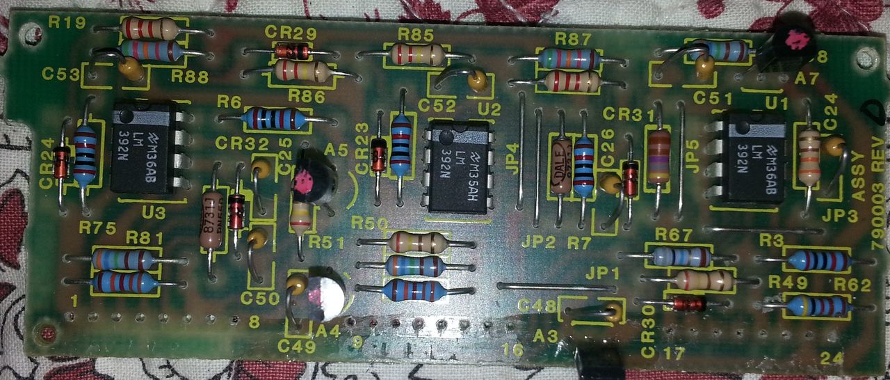
At first glance (the schematic was then a bunch of poorly made "Dave-CAD-like" sketches on several sheets), the exact role of the LM392 opamp was not clear to me, but when I redrew the schematic a bit more clearly, it became obvious it was some sort of current limitation circuit. And, sure, my problem could very well be a current limitation system being a bit zealous.
So I started to probe the resistors around the LM392 to check their values. And guess what? R7 was dead. It's a 20k 1% resistor, and it was not letting any current pass through.
What are the odd of such a failure on a PSU like that? Unbelievable! I was expecting the failure of a cap, of course, maybe an opamp or a diode, but not a resistor.
I have not yet bought a proper 20k stable 1% resistor (which I don't have laying around), but I've installed a pair of 1% resistors in parallel (can't remember the exact values I've used) to get a close 20k. And bingo! the HP8904A can output a nice 10Vrms again!
Of course, while I was digging around my PSU problem, the Schaffner power line filter died in a violent smelly smoky way (took a while to get rid of the smell).
Battery, RAM and software options
One of my goals when I looked into my two HP8904A was to check the on board batteries responsible for keeping the content of the memory.
This is a critical thing, since the content of the RAM must NOT be lost otherwise the device won't work anymore (the official procedure to change the battery involeve sodering a power source in parallel to ensure the RAM chip is always under power).
The HP8904A seems to be the first HP test equipment to have software-enabled options. The option activation depends on the serial number of the machine, which is also stored in this "non-volatile" RAM.
There is mainly one option one does not want to loose, it's the Option 1. It enables the Channel Configuration Mode Enhancement. It's the one that make the unit so handy (allowing to mix up to 4 waveforms).
I already cheated a bit back then. In fact, one of my 2 HP8904 came with no option, the other with option 1 and 2. Option 2 means it have a second analogic board allowing two separated outputs. So I used the serial number of the unit coming with option 1 on the other one, and bingo, this latest had then the option 1 activated also.
But I recently found on the EEVblog a thread pointing to an HP service document describing how to modify the correct byte in the RAM to activate all the options!
And the magic trick is:
Power-Cycle/Power-On
SHIFT, SERVICE, SHIFT, f4, 0, 9, 2, 4, 4, 8, SHIFT, SERVICE
NEXT, NEXT, NEXT, f1, 3, F, F, C
f2, F, F, f4, f4
Power-Cycle
That is: write the value 0xFF at address 0x3FFC.
The procedure to restore the serial number can be found in the service manual of the HP8904.
And in case of failed battery, the memory can be restored following this document
Next steps
The first thing I have to do is to replace my temporary fix with a new stable resistor.
I'll probably replace the power line filter of the other signal generator before it dies in a smoky way.
Then, I need to recalibrate these puppies, but I need to build a bit of confidence in my HP3456A DVM for this. But that's an other story.
I also want to replace the fans with some more recent and quiet models.