The HP5334A is a decent universal counter. It has a two 100MHz channels. Some models come with an optional third channel (1.3GHz), an optinal DVM, and an optional oven controlled oscillator. Unfortunately, my meter has no option at all.
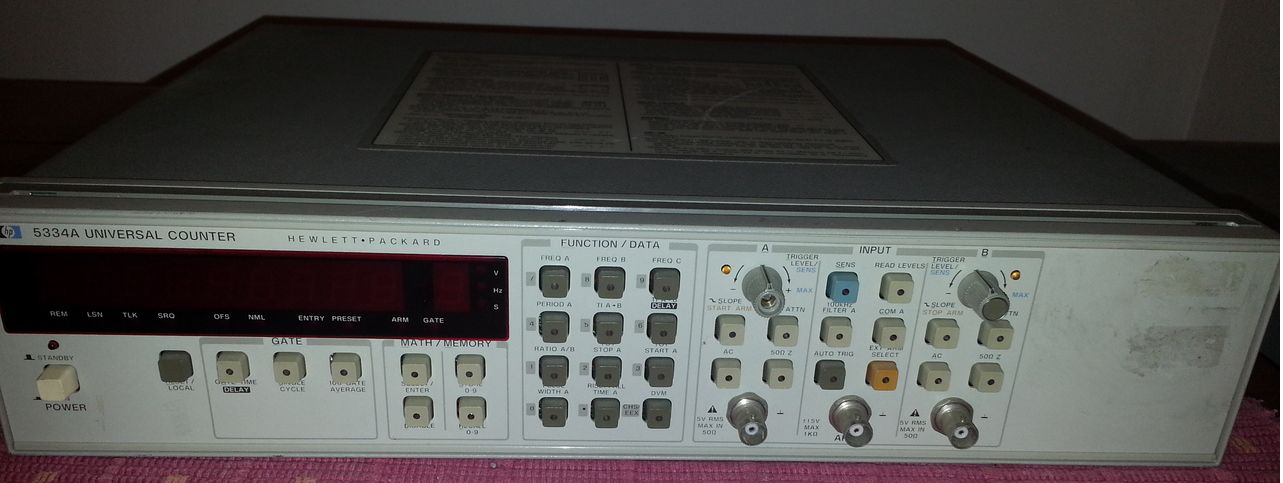
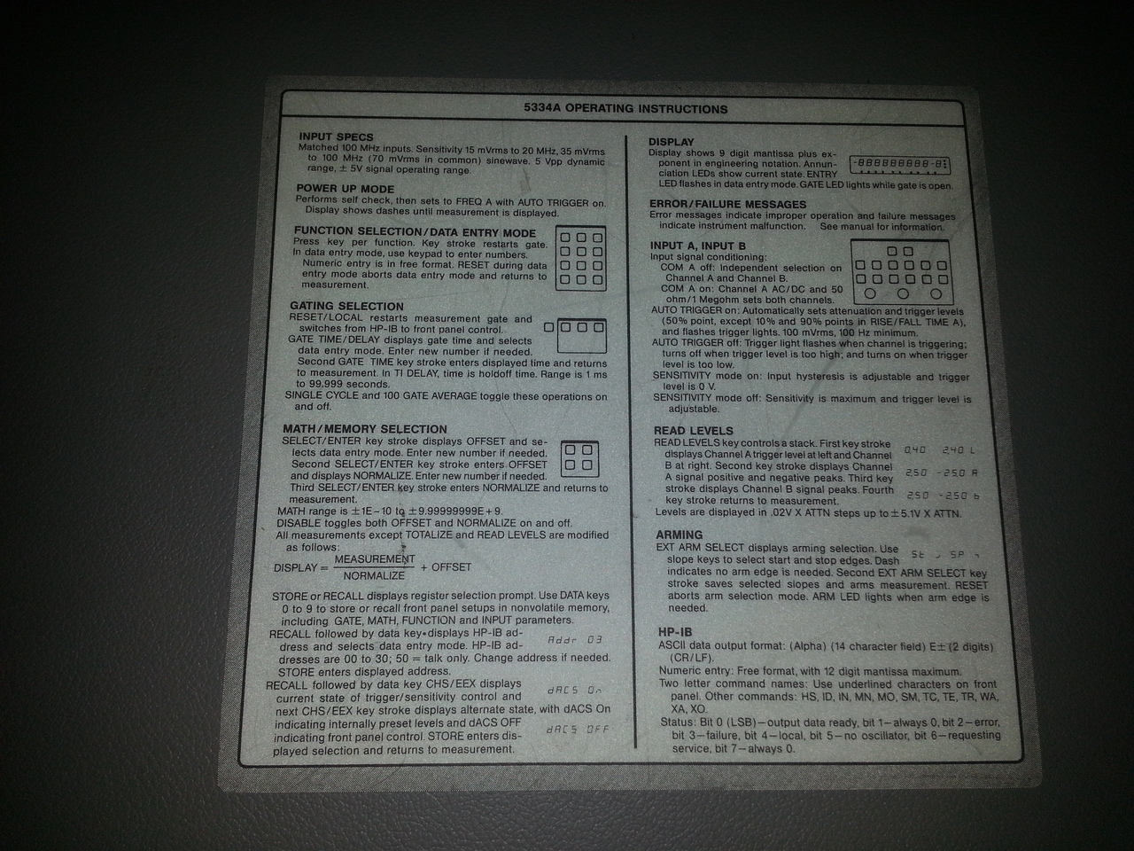
There is a nice quick instruction set printed on the top cover:
On the rear panel are 2 BNC (ref in/out and gate), the power socket and the GPIB connector. One thing is a bit annoying on this device, it's the fact that there is only one BNC for both the external 10MHz reference input and the internal 10MHz reference output, with a small Ext/Int switch to select the mode. So I have to reach the rear of the device to switch this later when I want to use my Efratom 10MHz reference standard (since I don't intent to keep it running every time I want to user the 5334).
When removing the covers, one can see:
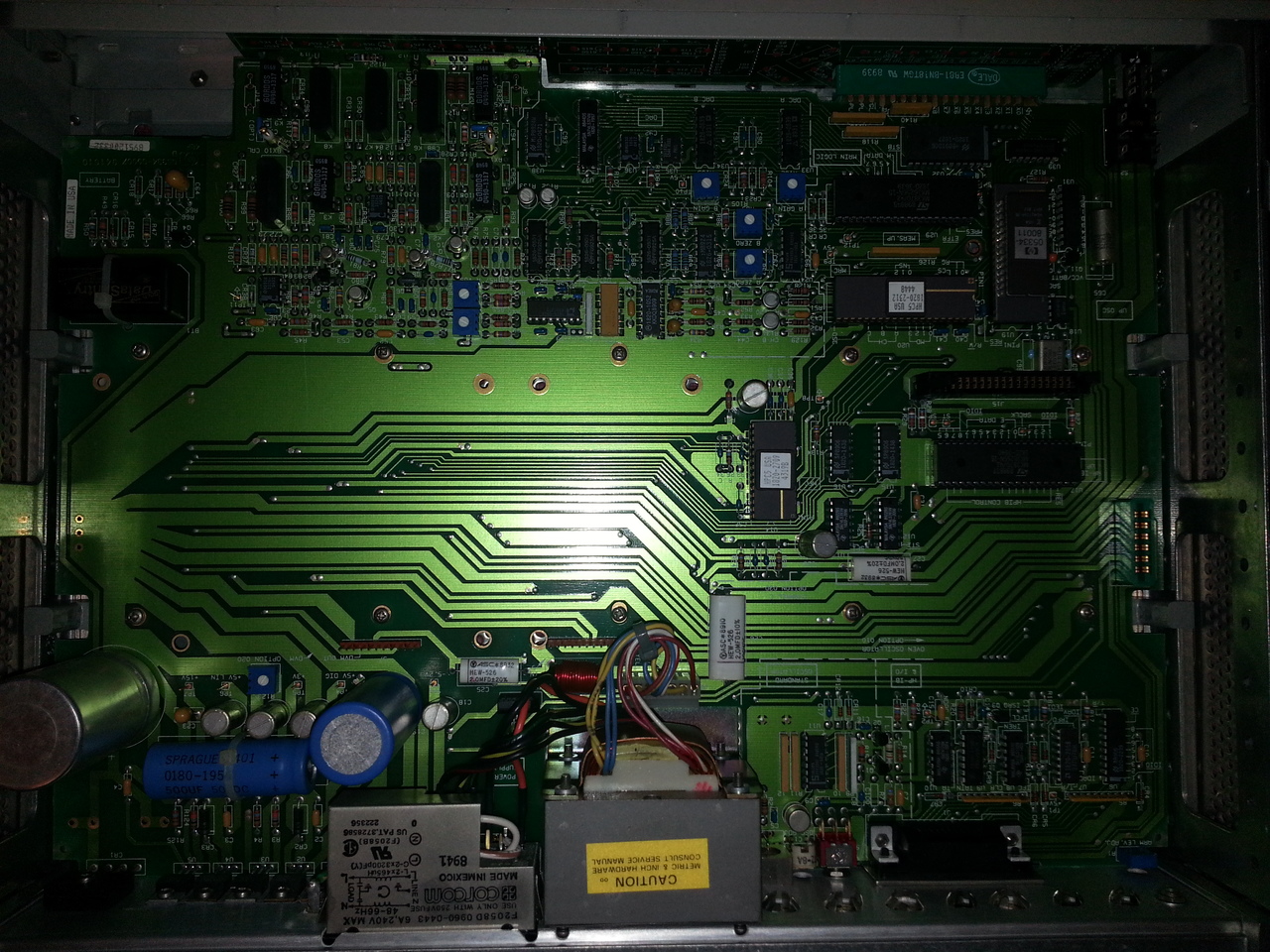
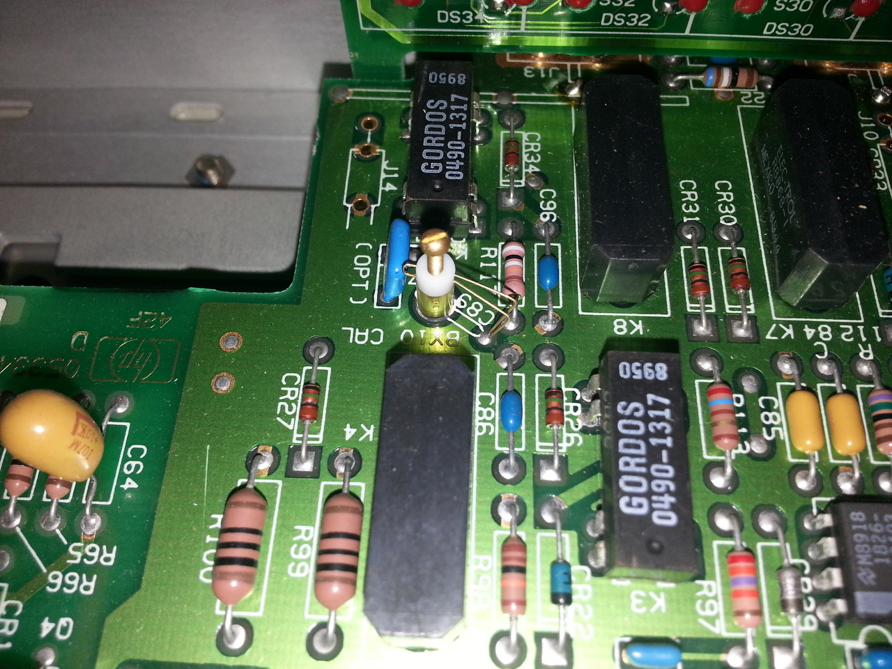
with a very nice star-shaped ground lattice. Among other interesting things are these funny little variable caps:
And as one may expect in such a device, no fan.
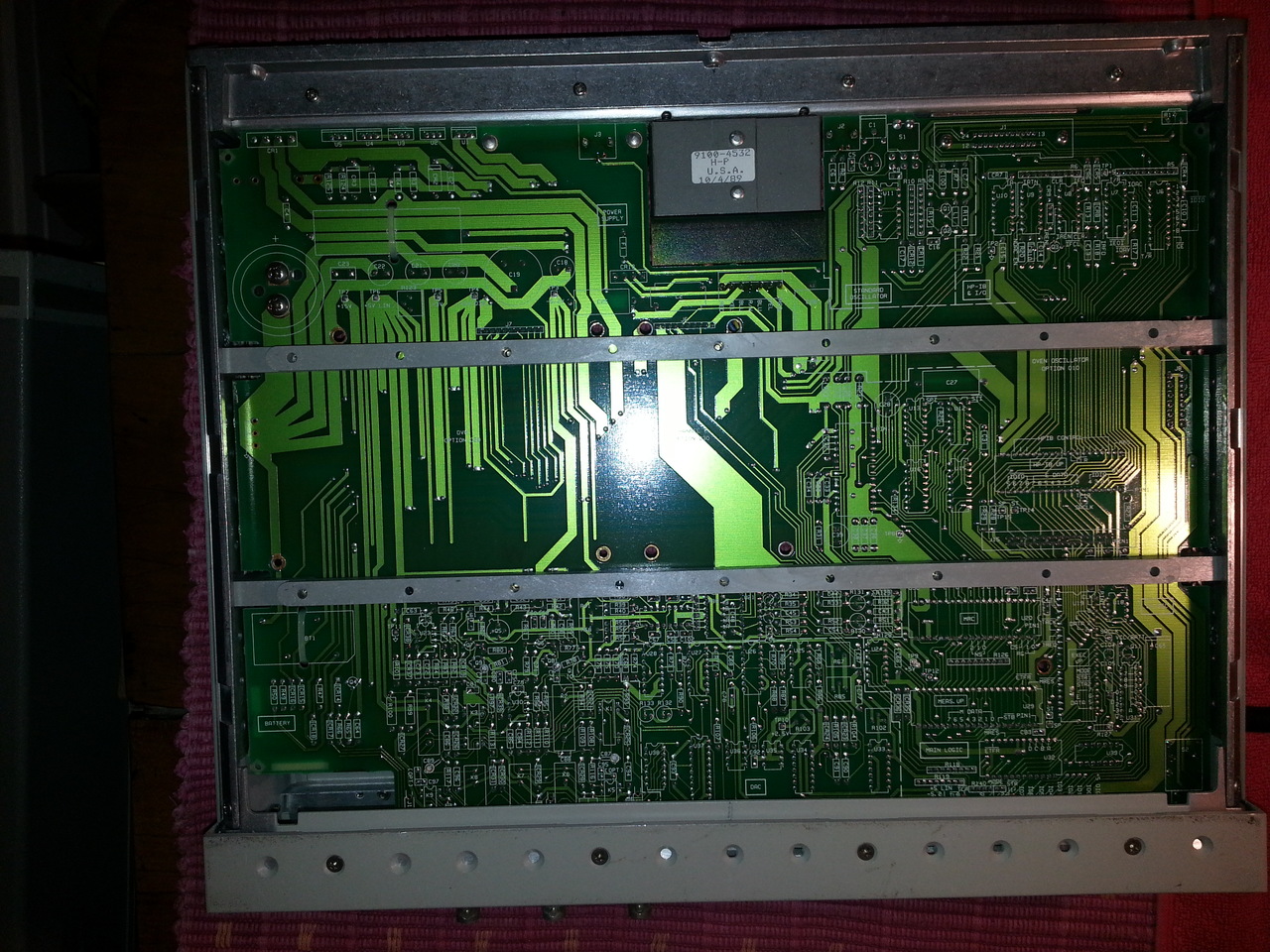
The bottom side of the PCB looks like:
Adjustment
My 5334 does not have the high stability timebase option (Option 010), so my counter's stability specs are:
- aging rate < 0.3 ppm per month
- tempco < 5 ppm (0°c to 50°C)
- line voltage < 0.1 ppm for 10% change
And it was not so out of specs:
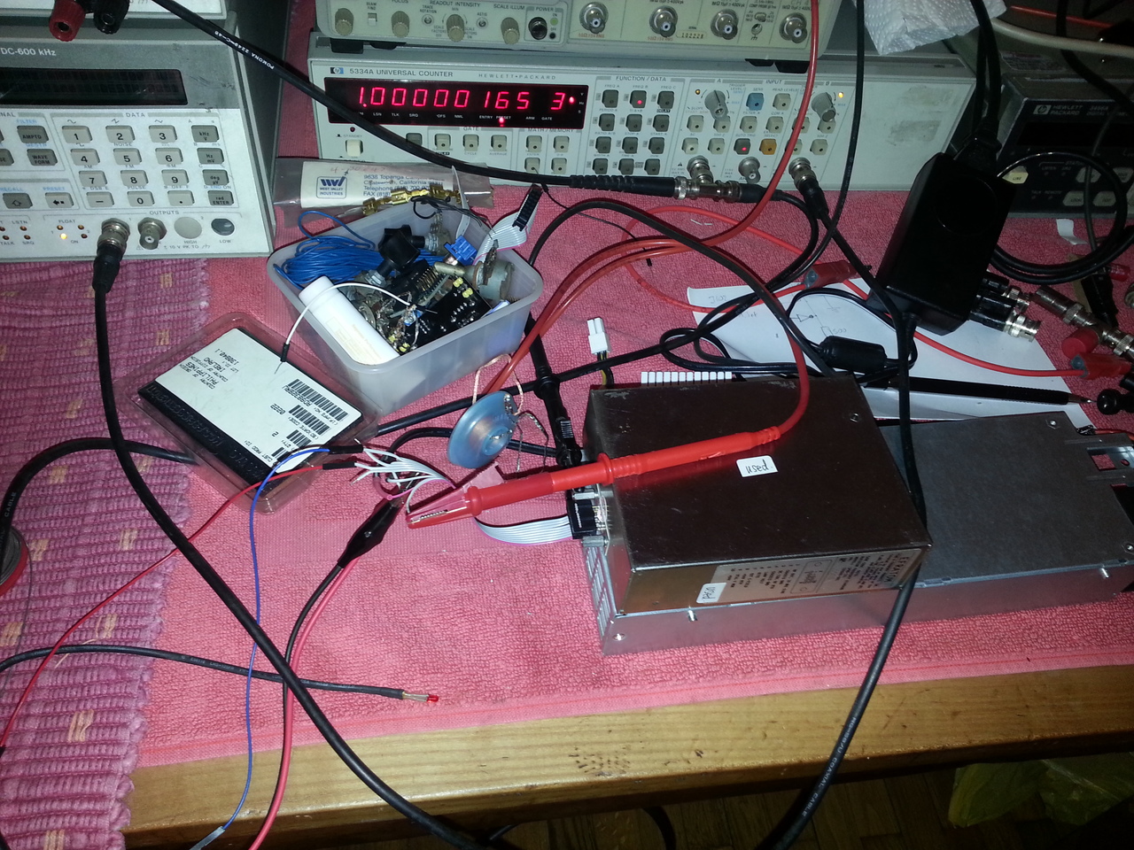
In this picture, the signal is a 1kHz sine wave generated by a HP8904A using my Efratom 10MHz reference standard as 10MHz reference, so it should be pretty close to a solid 1.000000kHz. The gate time delay is the default 0.3s.
On this device, the crital oscillator adjustement variable capacitor is accessible directly from the rear panel. I guess that without the high stability option, the 10MHz time base was not part of the calibration process and had to be adjusted quite often.
So I've used the rubidium reference standard to adjust the internal 10MHz oscillator and I have, for now, a mush better 10MHz internal clock (here we measure directly the 10MHz signal, and the gate time delay has been set to 1s, as described in the service manual when adjusting the oscillator):
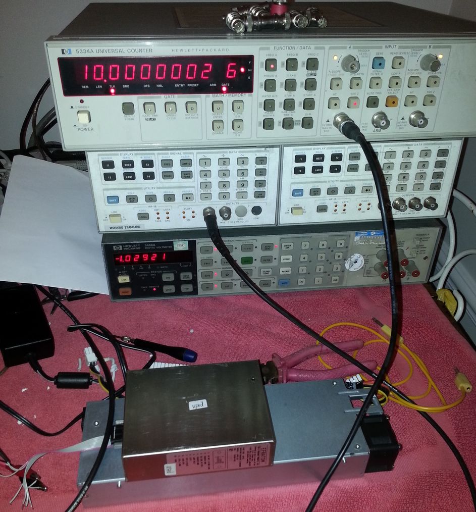
The adjustment capacitor is not fine enough to reach a spot 10MHz value, the best I could achieve is a 0.2Hz away from the expected value, which is quite excellent, actually.
But let's see within the next few days if it drifts a lot or not (as I am writing this, it has moved a tiny bit to 10.0000005 MHz... 0.5Hz off, something like 0.05 ppm).