I recently purchased a broken EIP 545B microwave frequency counter on ebay. It was very inexpensive (around 150€ delivered), but obviously, non working.
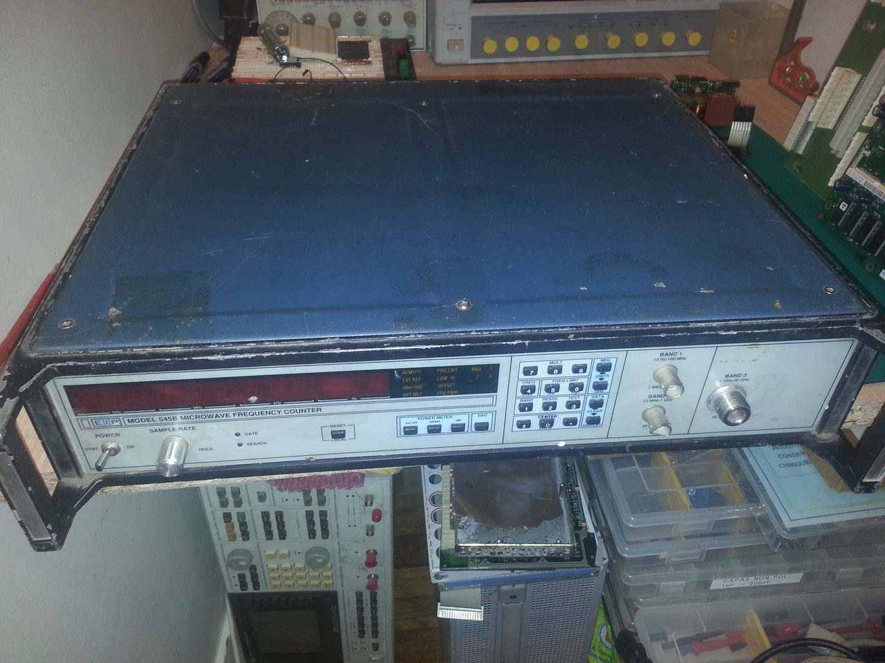
The device was described as "does not power up", an is clearly not in very good condition. Quite dirty, battered, with the band 2 BNC connector ruined.
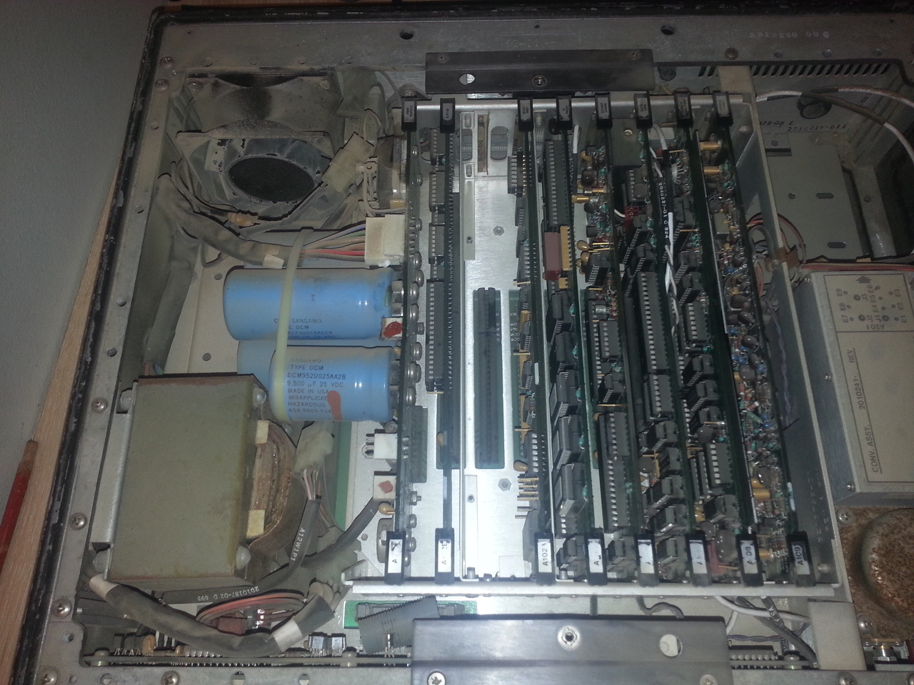
But inside, it was very dusty and a bit rusty:
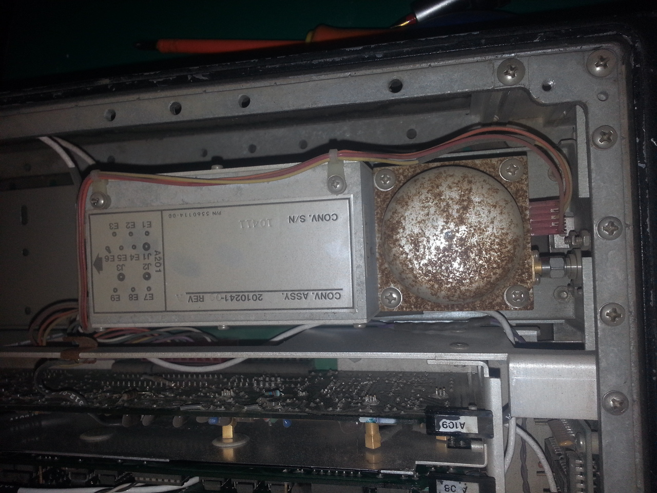
The YIG filter looking not so good:
I quickly checked, and indeed, nothing happened when I tried to power it up. In fact, the fuse was blown. So, instead of just give a try with a new fuse, I decided to disassemble it completely to clean it up, check the power supply independtly, then inserting the boards one at a time.
PSU
So the first step has been to check wether the PSU is working fine. Overall, it looks OK:
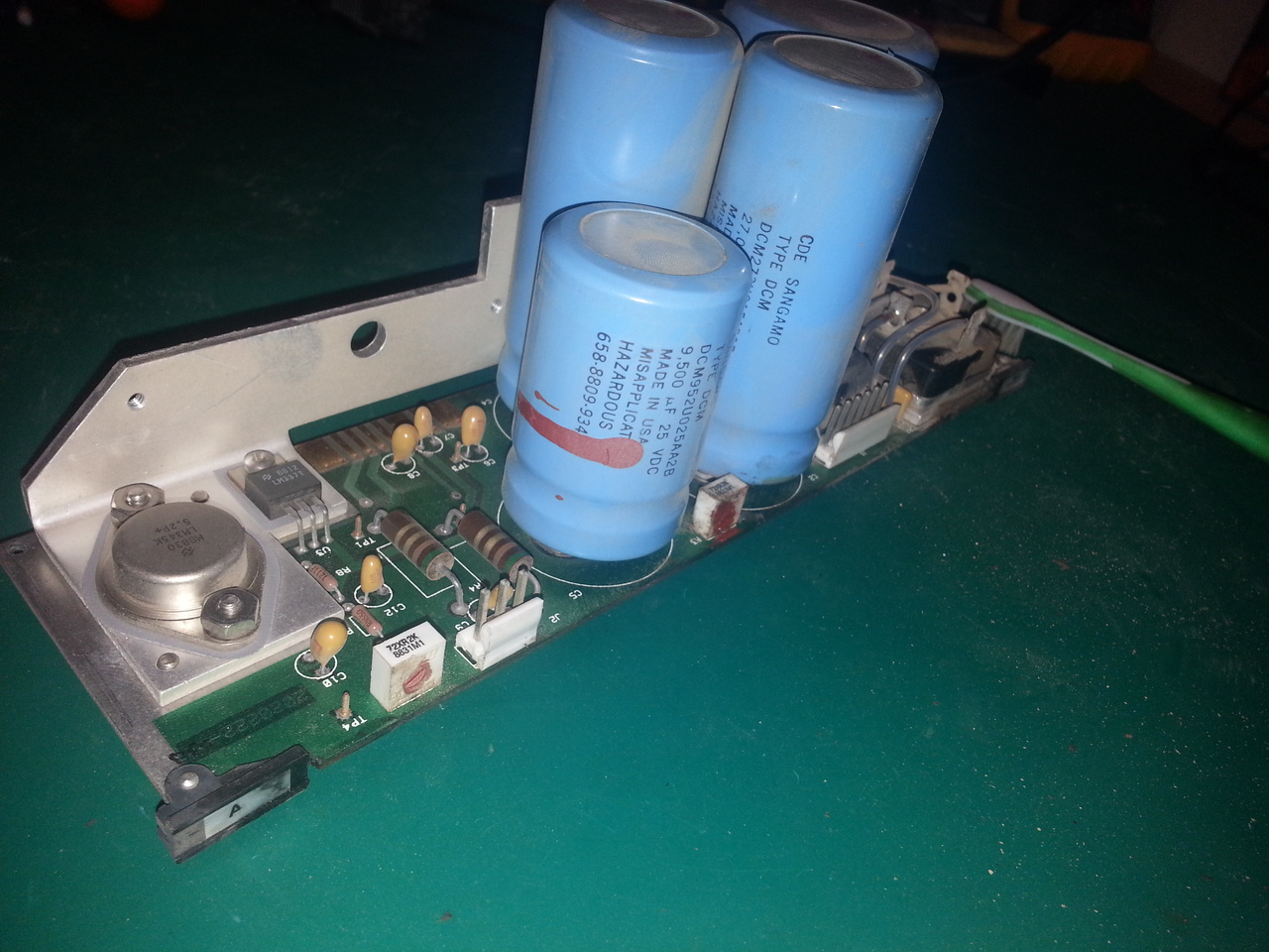
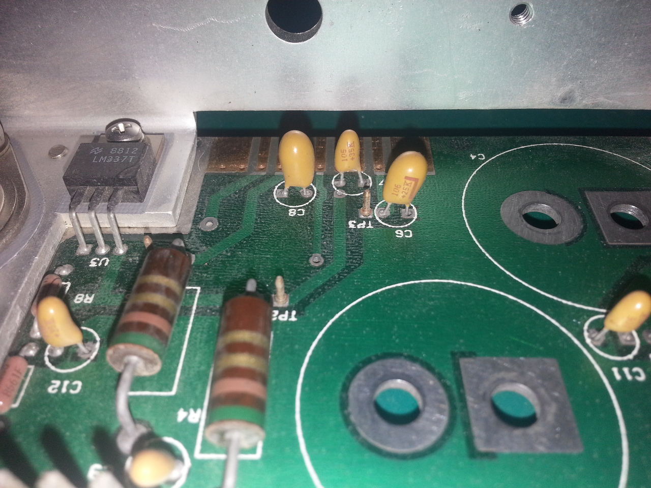
There are many tantalum capacitors in this unit, including on the PSU board:
But they seem OK, so I gave it a try with no load, but using a variac to rise the input voltage slowly:
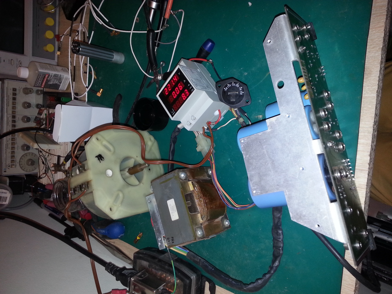
I plan to build myself a nice isolation transformer unit using this variac, a true isolation transformer I have and the power meter shown on this picture, but that's another story.
The results are ok so far, voltages are OK. The PSU seems to work just fine.
Cleaning the unit
The next step has been to completely disasseble the counter in order to clean it properly.
It's a quite simple unit, easy to disassemble, so it took me only a few hours to do so.
My only complain is to be obliged to disolder a few wires to disassemble the components from the back panel.
I'e washed every part I could in my kitchen sink, with dishwashing soap and a duster, includind the A100 interconnect board.
Other PCB board have been cleaned with a small tooth brush, some cloth, and isopropyl alcohol.
I also tried to remove a bit of the rust from the YIG filter using some scotch-brite, but I could not really clean it without disassembling it, and I'm not sure wether it is safe to open the enclosure of the YIG filter or not (if it's sealed with special gas for example). Also, I wanted to check if it works before doing anythno stupid.
Reassembling and testing
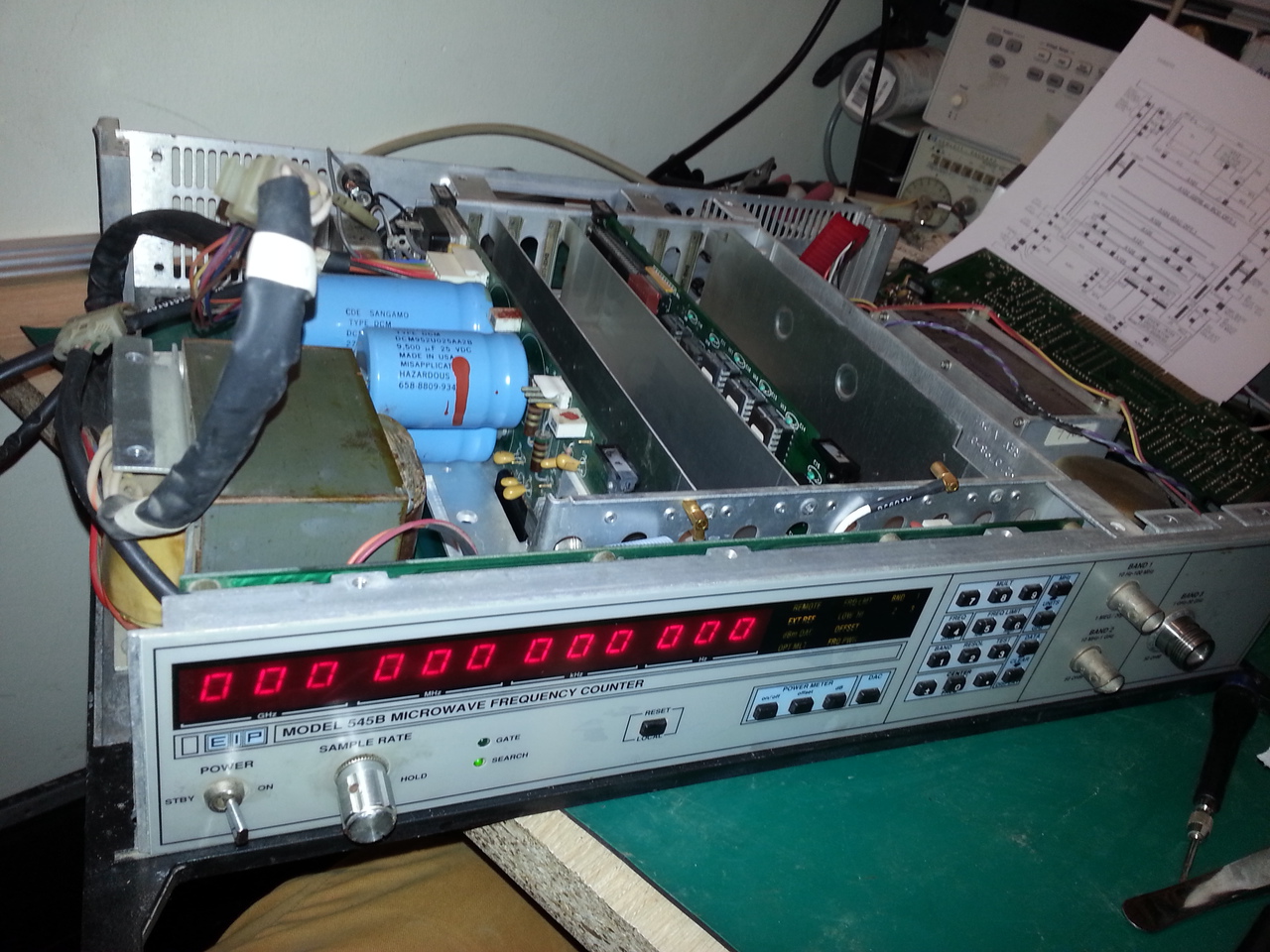
Then I started to reassemble the unit, just putting back togother the front panel, the CPU and the PSU.
Once powered, nothing happened, the display did not lit... It happened I forgot to put back the 7805 regulator dedicated to the front panel (and mounted on the aluminium chassis for heat dissipation). Doh!
Once fixed, the unit did power up, and reacted to some keys:
So far so good. Now the time for testing the other boards.
After inserting all the boards but the optional A102 GPIB board, the unit still powered up, but the keyboard was mostly unresponsive, and the "remote" led was lit. Putting back the GPIB board did the trick.
I also had to plug the 10MHz In/Out switch back (located on the back panel), since the default (open) position is for "External Reference".
Now I can interact with the device. In band 3, and I can hear a small noise, typical for a YIG coil sweeping the range... Good sign!
Let's put some signal, first a 6MHz on the band 1 input:
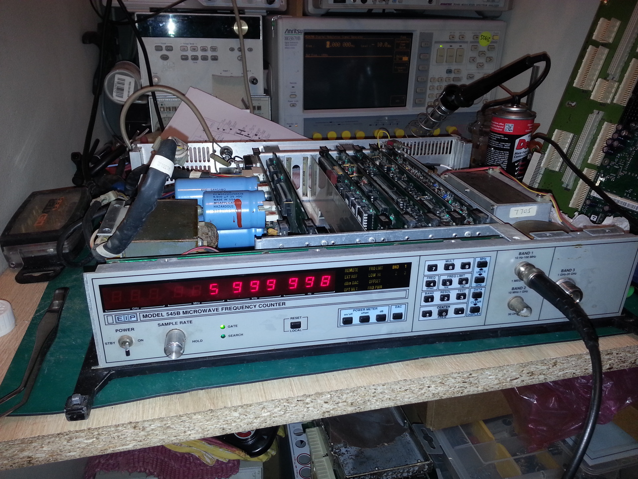
It works! I quickly checked band 2 (using a piece of wire since the connector is broken), and it seems to work fine. And band 3:
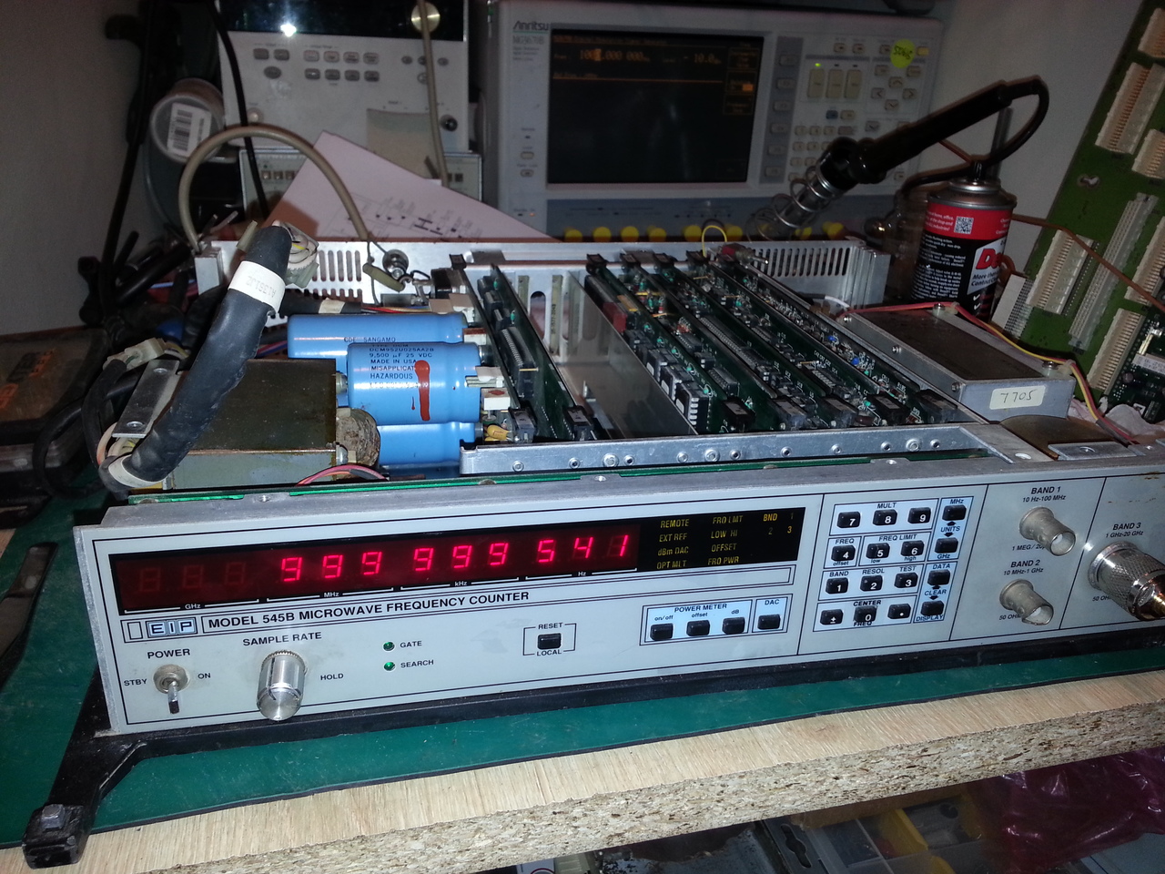
I've checked up 2GHz, the max frequency I can generate using my Anristu MG3670B signal generator.
A quick test showed that the sensitivity is not as expected: could not measure any signal below -12 ou -13dBm.
Next steps
Next steps for this unit are now:
- Finishing the repair, changing the broken BNC connector, the broken fan (which was in fact the culprit for the blown fuse), as well as, maybe, removing the rust from the YIG filter.
- Make some performance tests and calibrations (as far as I can do using my equipment).
- I also want to try to install the Option 2 (Power Meter). This procedure is pretty simple (as long as I manage to program a few 2716 EPROMs with my MiniPro TL866 universal programmer) and has been done by several people, but always on the 545A model, not the B model. Not sure if I can use the EPROM images kindly provided by GBPPR...