A few weeks ago, I purchased a cheap electronic load from AliExpress (this one to be precise). It's a ZHIYU model ZPB30A1. It's specifications are:
- constant current mode
- max voltage: 30V
- discharge current: 0.2A to 9.99A (+/- 0.7% + 1 digit)
- max dissipated power: 60W
- voltage measurement error: 1% + 2 digits
It supports 2 operation modes:
- electronic load: in this mode, you can set the current and the minimum voltage above which it beeps; in this mode, it display the measured voltage and set current.
- battery capacity test mode: in this mode, you set the discharge current and the lower voltage limit at which the discharge test stops. It displays the total discharged capacitu (in Ah) and energy (in Wh).
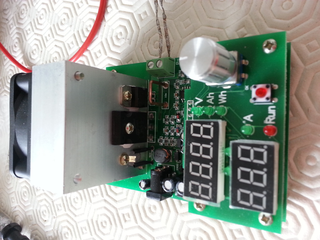
The device looks pretty nice and reasonably well built. It can do 4 wire measurements.
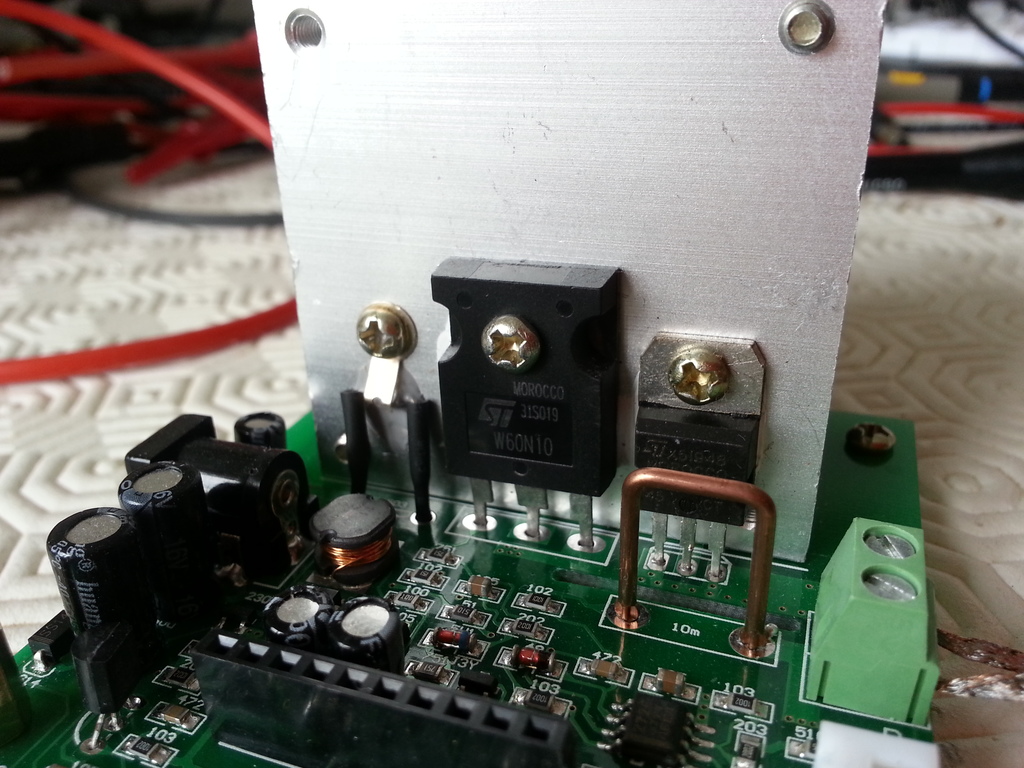
The device itself is built around a single ST W60N10 N channel MOS transistor (100V, 60A, 200W) and a STM8S005K6 microcontroller.
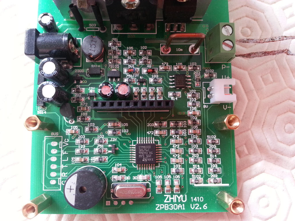
The shunt resistor is a 10mΩ wire. A very small value that explains the rather big minimal current of 200mA (which means a voltage drop as low as 2mV).
One nice thing with this device is the fact that every component value is written on the PCB: no need to use the magnifier to read the SMD parts values.
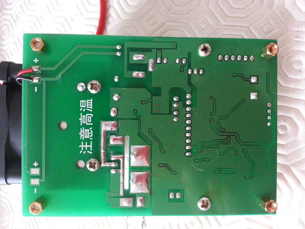
The bottom side of the PCB is pretty empty besides the ground plane.
The most annoying thing is the minimum current of 200mA, which pretty hight. It's obviously not designed for small battery or PSU testing.
Another thing is that its limited to CC mode only (does not provide constant resistance mode nor constant voltage). It's a bit unfortunate since it's probably only a matter of software.
Also, the usability is quite rough. For example, to choose the operating mode (between CC charge and battery capacity test mode), you have to power off the device and power it on holding the start/stop button down.
The last missing feature, for me, is that there is not "output" port allowing to capture the values when doing a battery discharge test. The good news is that there is unpopulated port. Looks like some ISP/serial port directly connected to the microcontroller. Pins are labelled as G, R, T, L, F and Vc. G stands for ground, and Vc is obvious. R and T might be Rx and Tx of a serial port. F and L are not obvious.
So I've probed a bit to see if there are any signals.
The overall (messy) setup was:
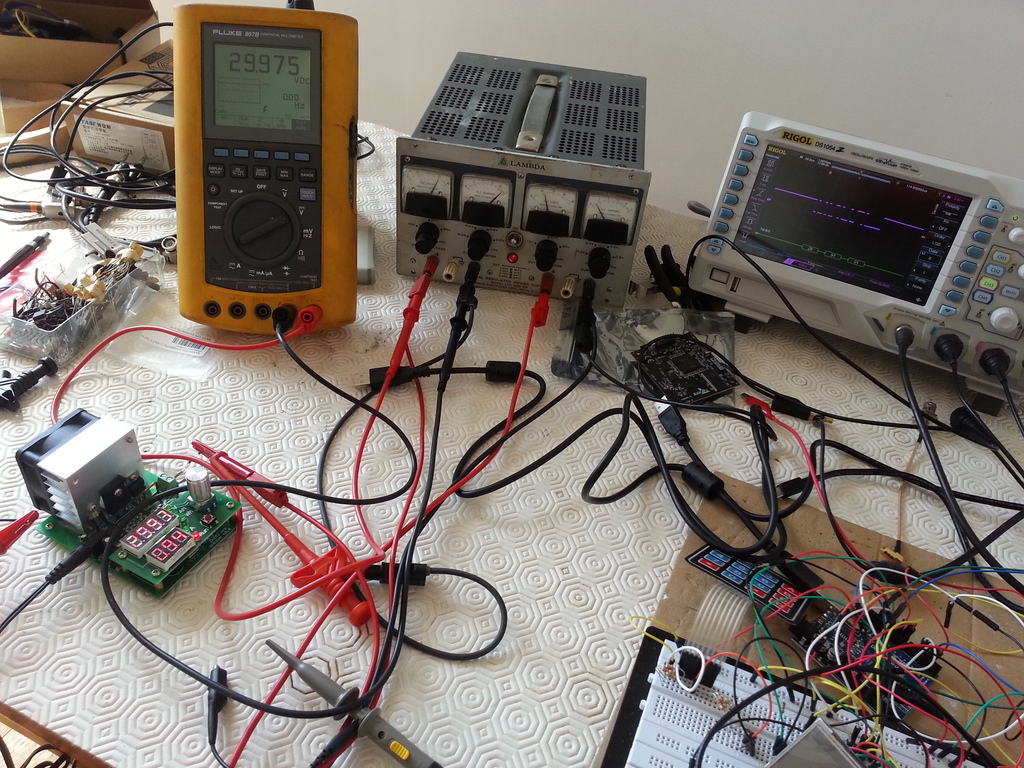
During this test, the electronic load was sunking almost 1A at 30V, thus dissipating around 30W. The MOSFET transistor was getting a bit hot. I measured 65°C with my cheap IR thermometer.
The F pin shows a square signal at 50kHz, and there is some activity on the T pin. I've used my new Rigol DS1054Z scope to try to find out if the signal is meaningful. And after playing a bit with the Serial decoder, I finally found that:
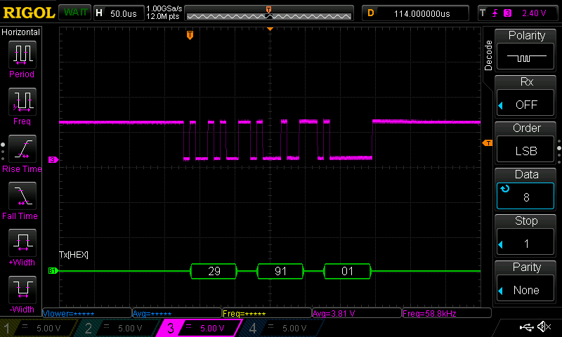
When the ZPB30A1 was actually set up like this:
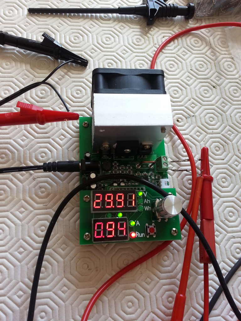
So the measured voltage is constantly written on the serial port at 115200 baud, 8N1. The third value is 1 when it is normally operating, and 0 when the voltage is below the limit.
However, in battery discharge mode, there is nothing on the serial line.
Now, I have to solder a socket in there. Then the next step will be to see if we can send commands to the ZPB30A1. I may need to learn a bit about the ST microcontroller...