In order to build a replacement display for the HP34970A data acquisition unit, I needed to understand the communication protocol between the CPU board and the front panel assembly.
General description
The unit is built with four boards:
- A1 is the main bard, with the PSU, the main controller and the floating logic,
- A2 is the front panel with the display and the keypad,
- A3 is the backplane on which I/O modules are plugged,
- A4 is the (optional) internal 6.5 digits DMM.
The commnucation between the different system blocks is done with asynchronous serial links. They use the rather uncommon bit rate of 187500 baud, with a classic 8E1 schema (note the even parity bit).
The CPU <-> Display Panel communication protocol
The communication protocol between the main controller (CPU) board and the display panel (DP) consists in "datagrams" sent using the general pattern:
when a device (CPU or DP) wants to take control of the communication bus, it sends a Start of Transmission (SoT) signal (0x66),
each sent char (but the end of transmission) must be acknowledged (ack value may vary),
at the end of a communication, the initiator send a "End of Transmission" (EoT, 0x55). This sent value is not acknowledged.
the keyboard can interrupt a CPU->DP communication in progress by not acknowledge a received byte, but sending a SoT instead of the expected ACK value,
acknowledge values are:
one-complement of the received SoT byte, so
- 0x99 for the 0x66 SoT byte and
- 0xCC for the 0x33 SoT byte.
0x00 otherise
a special packet is sent by the Display Panel at startup, which SoT value is 0x33, which does not seem to follow the general pattern in which the first value after the SoT byte is the number of arguments.
Initialization sequence
The initialization transmission is:
If a key is pressed during while powering the unit on, then the initialization of the Display Panel is frozen (with all elements of the display lit) until the key is released. In this case, the initialization packet adds the key code of that key, typically used with the Shift key pressed in to force a full test of the device (in this datagram, 0x0C is the keycode of the Shift key):
Shutdown sequence
CPU -> DP trasmission
The CPU->DP transmission protocol looks like:
Two (or more) datagrams can be transmitted in a single "transmission", ie. without sending the EoT byte, eg.:
DP -> CPU transmission
When the user press a key on the front panel, a slightly simpler "packet transmission" occurs:
Commands
The known command bytes sent by the CPU for now are:
| 0x00: | show text on the main display. N arguments; the characters to display. |
|---|---|
| 0x0C: | show text in the 'channels' area. 3 arguments; the digits to display. |
| 0x0A: | indicators (or flags) to display. 4 arguments; the flag bytes. |
| 0x08: | to set an indicator in low bright mode. 1 argument; the number of the indicator dimm. |
| 0x09: | to set an indicator in hight bright mode. 1 argument; the number of the indicator to highlight. |
| 0x01: | clear the 'shift' button. Typically sent as 0x01 0x01 0x0E. 1 argument; 0x0E to clear the 'shift' flag. Other values unknown. Probably the bit position of the flag to clear. |
| 0x02: | might be a reset or clear for the front panel (typically sent as 0x02 0x01 0x0C packet). 1 argument; unknown. |
| 0x86: | shutdown. 0 argument. |
| 0x0D: | set char at pos dimm (eg 0D 01 02 55 = cursor on the 3rd char) |
Sending data to the main display
The main display consist in 13 17-segments digits, in which the character is displayed by a main 14-digits, and the punctuation with 3 segments (2 dots and a comma, allowing to represent the signs ".", ",", ":" and ";"). Punctuation signs are also very close to the preceding chracters.
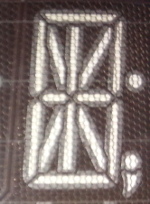
The command used to send text to the main display is 0x00. The character 0x09 (tabulation) has a special meaning: it marks the beginning and the end of a part of the text to be displayed darker than the usual. This is used to emphasis a portion of the displayed text. Also, as the punctuation signs do not consume a digit, the displayed text can be larger than 13 characters.
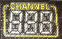
Sending data to the Channels display
This area only allows to display 3 7-segments digits. The command is 0x0C, the payload is thus 3 bytes long.
Flags
The display also has several flags. Display flags are selected by sending the 0x0A command. The payload is 4 bytes long. Each bit of these 4 bytes represent a flag on the display.
Let's consider the following (we don't represent the acknowledgements here):
The 29 flags I've identified are (should be complete):
Keypad
the keycode byte consists in:
| Bit 5: | is set when the key has been pressed while 'shift' indicator was stil active. |
|---|---|
| Bit 6: | is set when the key is released, and clear for the key pressed event. |
| Bit 7: | of the key event byte is set high for the knob key events. |
The key codes are:
| 0x00: | View |
|---|---|
| 0x01: | Mon |
| 0x02: | Sto/Rcl |
| 0x03: | Scan |
| 0x04: | Alarm |
| 0x05: | Mx+B |
| 0x06: | Measure |
| 0x07: | Interval |
| 0x08: | Card Reset |
| 0x09: | Close |
| 0x0A: | Open |
| 0x0B: | Read |
| 0x0C: | Shift |
| 0x0D: | Write |
| 0x0E: | Left |
| 0x0F: | Right |
| 0x10: | Advanced |
| 0x11: | Step |
| 0x80: | Knob right |
| 0x81: | Knob left |