As explained in the previous post in this series, I've started to sniff the serial protocol between the main board and the display panel so I can replace the failed VFD by an OLED or TFT display managed by an arduino or similar.
Protocol
The serial communication takes place at a rather unusual speed: 187500 bit/s, otherwise, a 8E1 scheme (with even parity bit).
The protocol consist in a transmission frame with a start of transmission handcheck, some commands with arguments, and an end of transmission packet.
Each transmitted character is acknowledged by the receiver, either by a <0x99> (for the initial handcheck) or by a <0x00> for the other ones..
I've only probed the CPU->DP communications. I don't really care the other way fr now since I plan to keep the original 80C51 so it manages this protocol and handle the keyboard.
In the direction CPU->DP, we can find:
- <0x66>: start of transmission, must be acknowledged by a <0x99> by the receiver; this start of transmission is then followed by a "command":
- <CMD> <NCHAR> <CHAR1> ... <CHARN>: the command byte is followed by the numer of characters sent as argument, then the characters themselves.
- <0x55>: end of transmission.
I've only identified 3 commands for now, but these are the most important ones:
- 0x00: send the chars to the main display
- 0x0C: send the chars to the secondary channel display
- 0x0A: set the display indicators
Main display
Characters are simply sent to the display. However, to specify that a part of the string to display should be less bright (usually, the selected option is bright and the other ones are dim), the CPU insert a special character (need to check which hexadecimal value it is) at the beginning and the end of the dim part of the string.
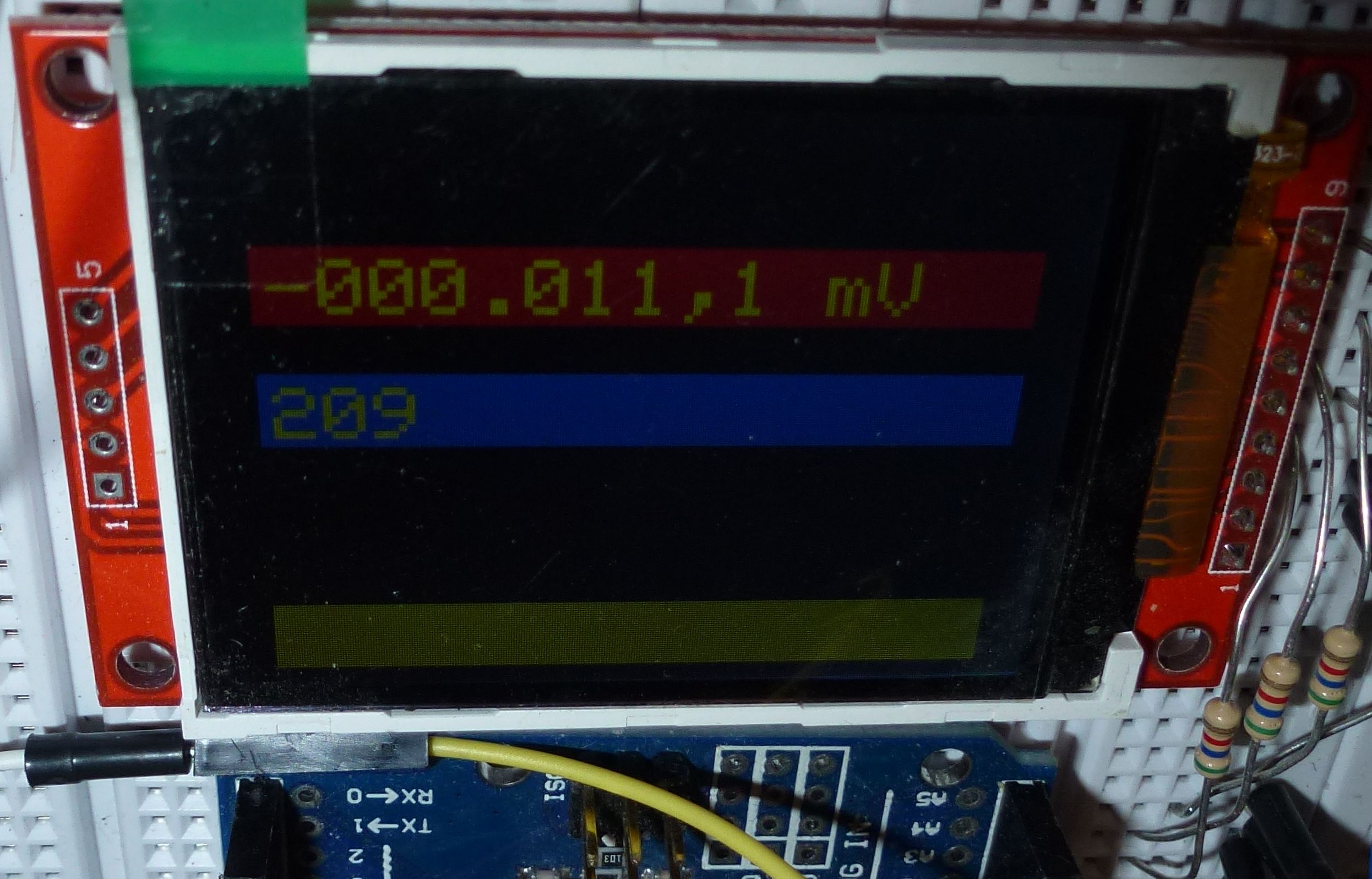
Channel display
Seems there is nothing special there. The frame payload always consist in 3 characters (the 3 digits).
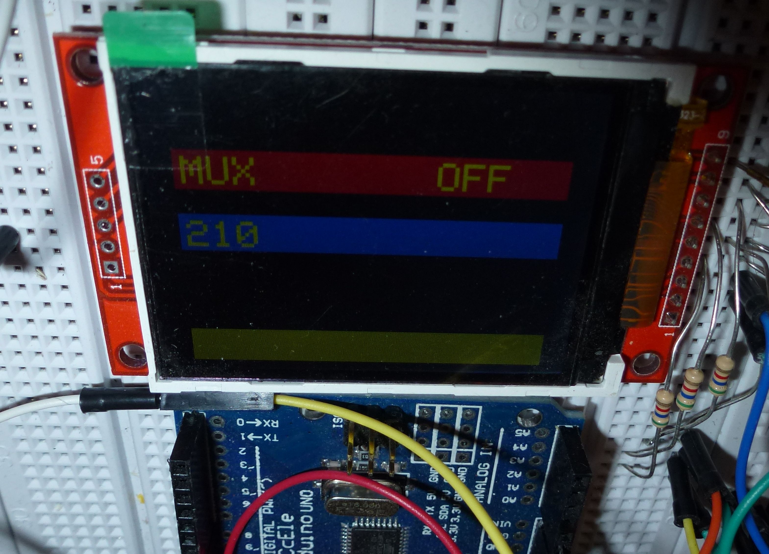
Indicator flags
The indicator flags are always sent as 4 bytes, each bit controlling one indicator.
The indicator flags I've been able to identify so far are below (please see this page for the complete protocol description).
Let's say the frame is: <0x0A> <0x04> <F1> <F2> <F3> <F4>, then:
- F1.8 =
- F1.7 = HI
- F1.6 = Alarm
- F1.5 = LO
- F1.4 = Channels
- F1.3 = Channels box
- F1.2 = Mx+B enabled
- F1.1 = Alarm enabled (or the alarm frame)
- F2.5 = 4W
- F2.4 = Alarm 1 ?
- F2.3 = Alarm 3
- F2.2 = Alarm 4
- F2.1 = Alarm 2
- F3.6 =
- F3.5 =
- F4.8 =
- F4.7 = CONFIG (not sure)
- F4.6 =
- F4.5 = MON
- F4.4 = VIEW
- F4.3 =
- F4.2 =
- F4.1 =
Quick prototype
With this very incomplete reverse ingeeniring of the communication, I have enough meat to try a quick prototype.
I've used an Arduino Uno and a cheap 3.2" TFT color display. As I wanted to have my serial protocol to debug the code for the beginning, I've used the SoftwareSerial library for this prototype.
The result is this beautiful clean setup:
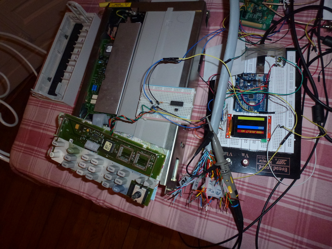
As you can see, it works: I have the main content od the VFD display on my TFT module!
The job is far from finished however: I still have to figure out how the "annotation" flags are encoded and display them, and most importantly, I have it make it work with the hardwre USART of the mega328. This seems to mbe necessary because I have glitches sometimes. But I'm very happy it worked almost at my first try. I was quite surprised since the baudrate is above the maximum officially supported one (115200).
I'll release the code of the prototype any time soon.