I recently "scored" a HP 34970A with the DMM included and 2 plugin cards (HP 34901A and HP 34907A) for less than 200€. The plugins should be in working condition, but the main switch unit was almost "given" with the plugin modules since it is non functional.
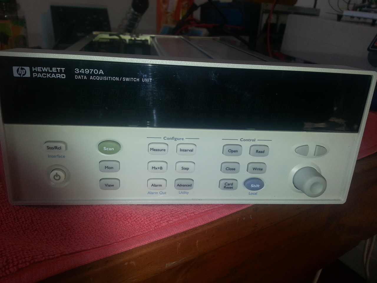
It's in very good shape, the front panel and the push buttons are clean. The knob is nice but it has a rough step when turning it for a complete revolution.
When powered up, however, things are a bit nastier... The VFD is, as often with these equipment, very dim and the digits tend to puke on the others. In fact, it's mostly unreadable, and the unit beeps several times, signs of errors (which I cannot really read them see on the display).
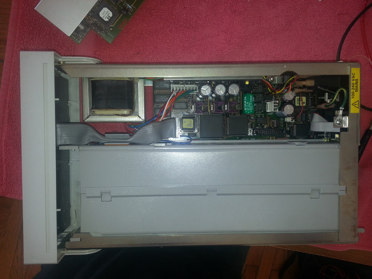
Internals
The unit consists in 4 parts:
- the main logic/cpu board on the bottom left side,
- the DMM module, juste above the main board,
- the frontpanel and
- the back plane where plugin modules are connected.
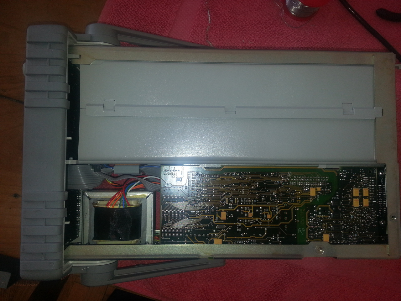
The front panel hold the keyboard, the rotary encoder and the diplay system.
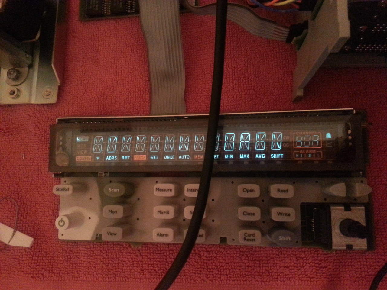
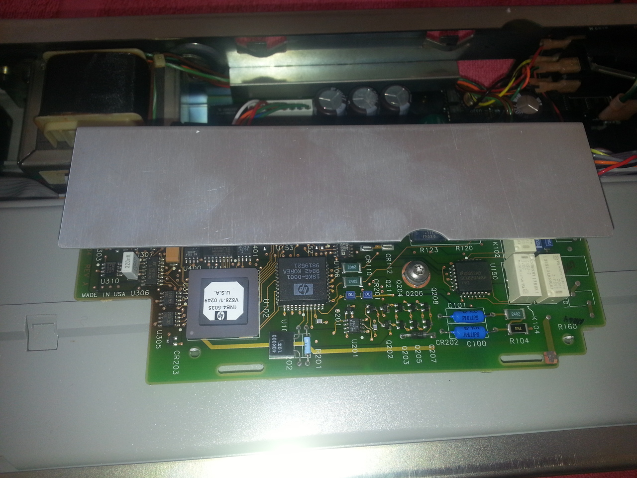
The front panel is managed by a 80C51 (a 87C51 actually) microcontroller. It's responsible for handling the keyboard and feeding the shift registers of the VFD drivers (a pair of HV518PJ). The communication with the main CPU is a serial line with opamps to adjust the signal levels.
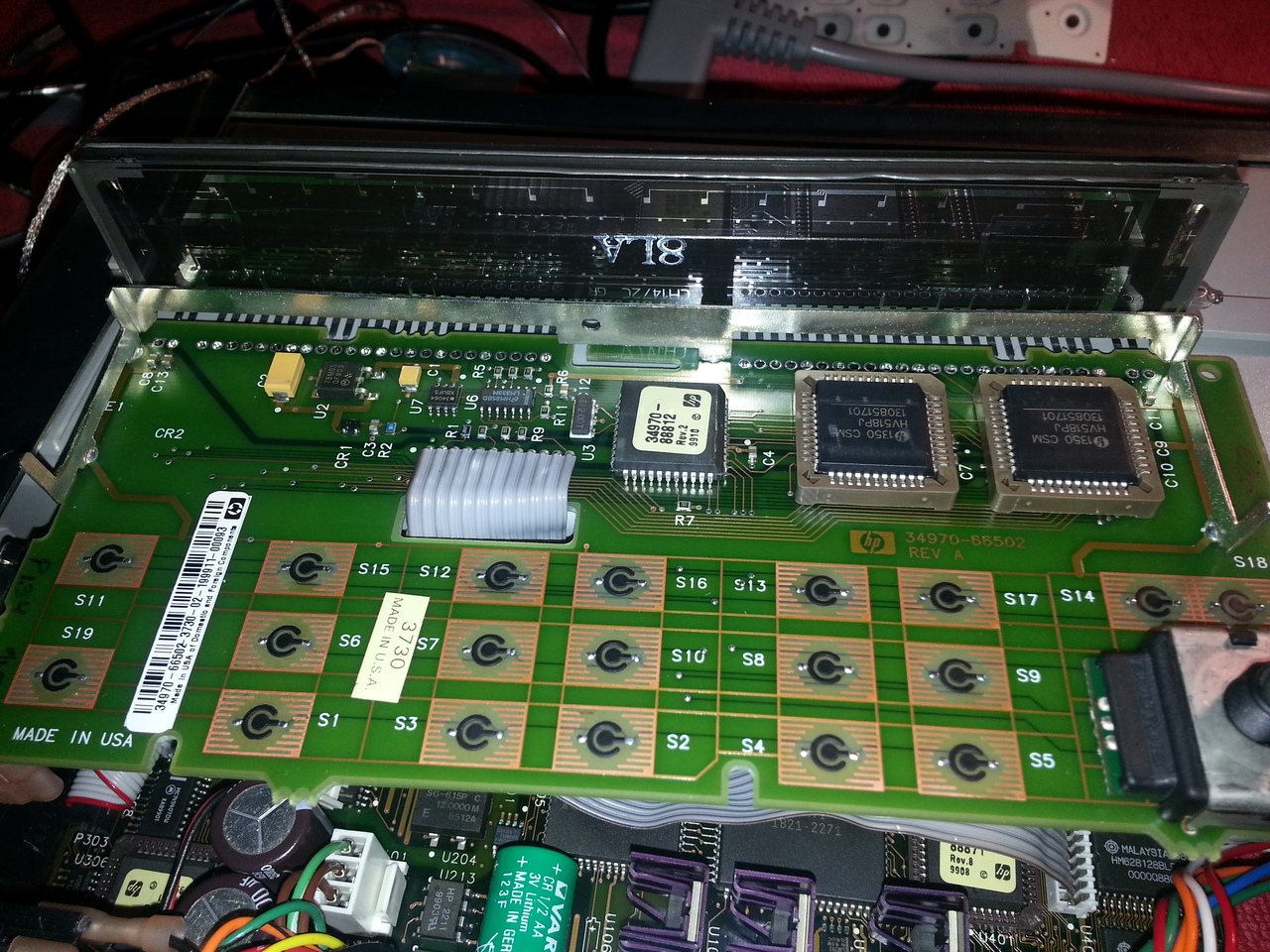
The chips are PLCC44 located under the VFD are the drivers:
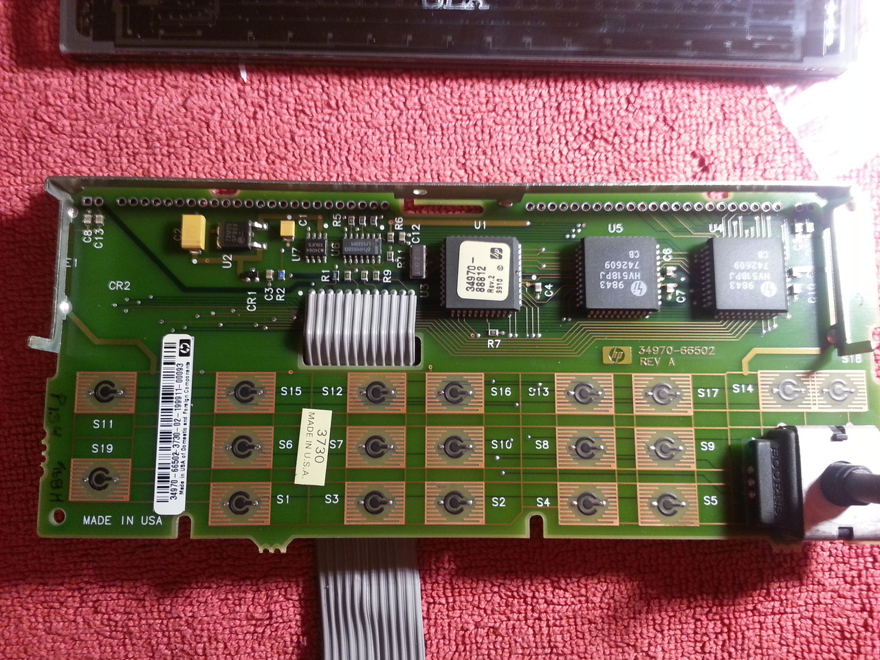
On my unit, the voltage levels for the VFD are fine. I suspected that one of the 2 VFD drivers (the one responsible for driving the grids) were partially failing, so I ordered a pair of new drivers, as well as some PLCC sockets. It was my first real smd revork. I though that it might be easier to cut the pins of the soldered chip, but it was not a good idea, I peeled 2 pads on the PCB. Thanksfully, they were not broken. So I've undoldered the other VFD with my new cheap hot air soldering station, and it's been way easier and did not damage the PCB at all... Lesson learned.
After that first real SMD unsoldering experiment came the first SMD soldering: install the plastic made PLCC sockets... I was not sure wether to use the hot air gun or my Weller soldering iron, nor what a correct temperature for the hot air station whould be adequate. The informations on the socket datasheet were not very clear to me.
So I gave a try (I think at around 280°C). The sockets seemed properly soldered, but in fact, a few pins were not making contact. So I decided to cut the bottom of the socket (which is essentially useless) so I can more easily rework these "cold" pins with my soldering iron.
The tricky part of installing these PLCC sockets is that decoupling capacitors (C6, C7, C9 and C10) are a bit too close, so I had to move them.
Now I had to try to rejuvenate the tungsten filaments. Like for old CRT (and even for triodes), the filament, which is responsible for emiting electrons toward the anode (coated with phosphor) tend to be polluted and loose their emissive power. A common trick to "clean" them is to apply a much higher voltage than rated so they shine for a few seconds. One mst be careful not to burn them, otherwise the VFD is definitively lost.
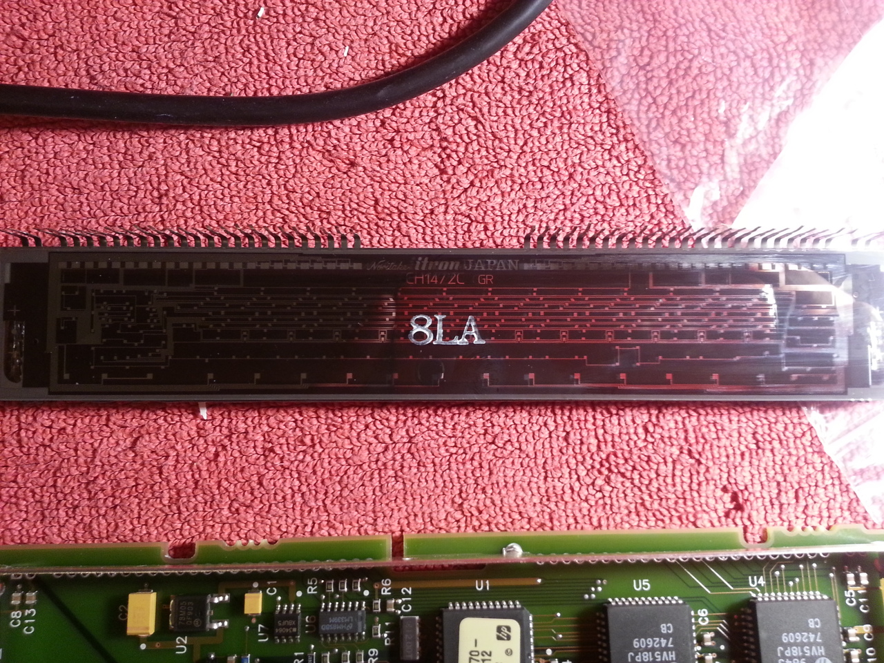
So I tried such a rejuvenation on my VFD module. I wasn't sure what color the filaments must be heated to (between a light orange to an almost white yellow). I was doing this using my Lambda PSU raising the voltage while looking at the filaments.
The results are very disappointing. The VFD is a little bit brighter, but the spilling over between digits is now much worse...
I guess this VFD module cannot be saved, after all...
So I've been thinking of a plan B, and I think I'll try to replace the VFD display with a blue 256x32 OLED module. It's smaller (I cannot find a module near the size of the VFD display), but it should still be quite readable. Indeed, that requires a bit of work: I plan to build an arduino-based adapter (using an arduino micor) that will take place of the VFD drivers (then be fed by the serial-to-shift registers outputs of the 80C51). One other solution is to replace the 80C51 with a newly programmed one, but I think reverse ingineering the serial communication between the front-panel microcontroller and the main CPU would require much more work. Since it's a 87C51, I doubt I can easily dump it's ROM...
Meanwhile, next step is to take care of all these errors.