This is the part 4 of the series about my HP 3562A Digital Signal Analyzer, quickly describing the HP 1345A Digital Display unit as well as the repair I had to do on it.
Display
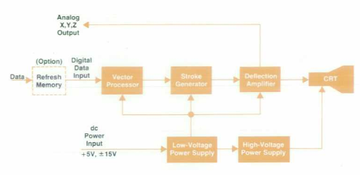
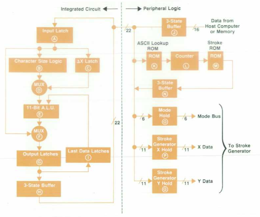
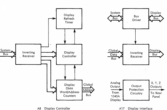
The display unit is a HP1345A Digital Display without the option 714 (wich adds a 4K x 16 bits Vector Memory), so it must driven by a dedicated display controller (which is on the A38 memory board):
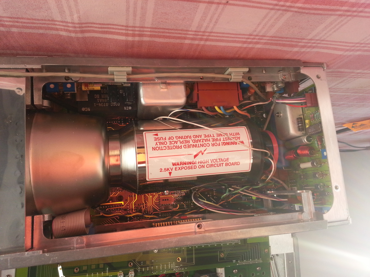
The unit is a 6 inch monochrome display producing true vector graphics with a resolution of 2048x2018 points. It can display up to 3226 inches of vectors at 60Hz. It also embeds a character generator.
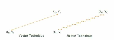
It's a true vector display; vectors are drawn by moving the CRT beam on the screen (it's not a pixel based display).
It can diplay:
- solid lines
- solid lines with intensified end points
- short dashed lines
- long dashed lines
- dots at end points
with 3 differents visible brightness levels. It also allows to specify 4 beam velocities:
- 0.13cm/µs
- 0.25cm/µs
- 0.38cm/µs
- 0.51cm/µs
Allowing more brightness control of the vectors.
If not connected with a controller, it shows a test pattern for adjustments.
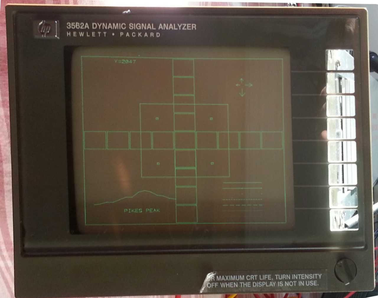
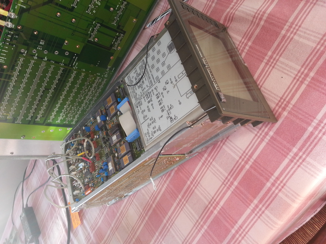
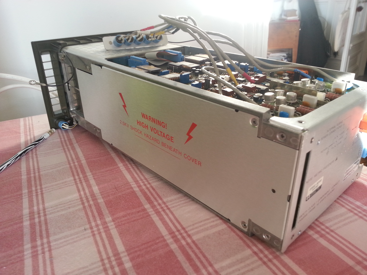
The unit looks like:
Adjustment and repair
While the instrument was apart, I wanted to see if I can recalibrate the display, especially try to adjust the overall brightness of the CRT since mine is a bit dimm (I have to set the intensity knob FCW to see the whole picture). I also wanted to improve a bit the focus and precision of the lines.
So I took the display unit off the instrument, which is straighforward, powered it using my benchpower supplies, and began to read the adjustment procedure and turn the pots, when suddenly the display shut off.
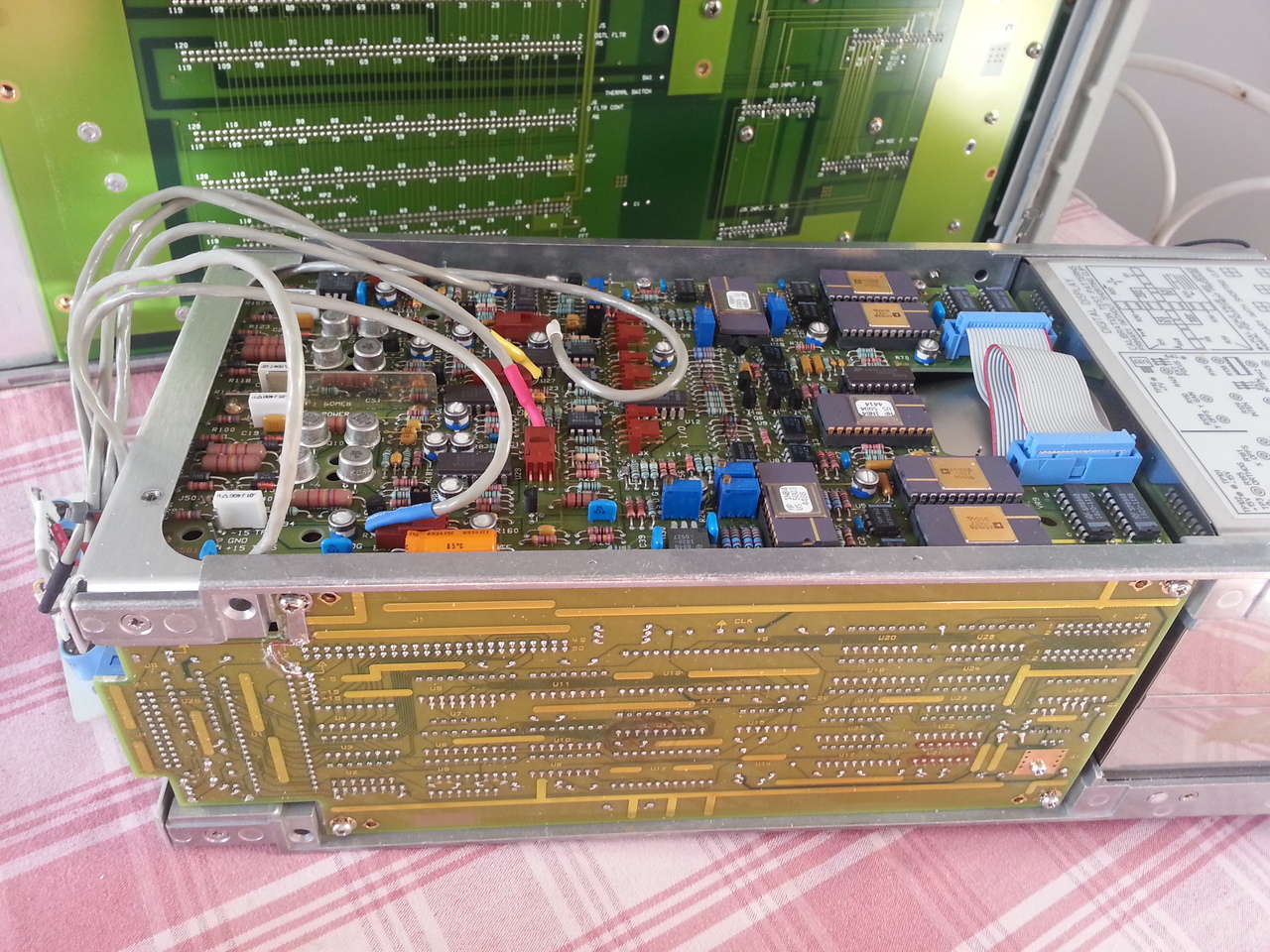
Using an ohmmeter, the diagnostic was easy: the +15v and -15v rails on the A1 board were short. Fortunately, the schematic is available, so I started to look for all decoupling capacitors (directly connected between a power rail and the ground). It took me a little while before identifing the real culprits, since the only solution to check them is to desolder (at least one end): A1C45 and A1C48.
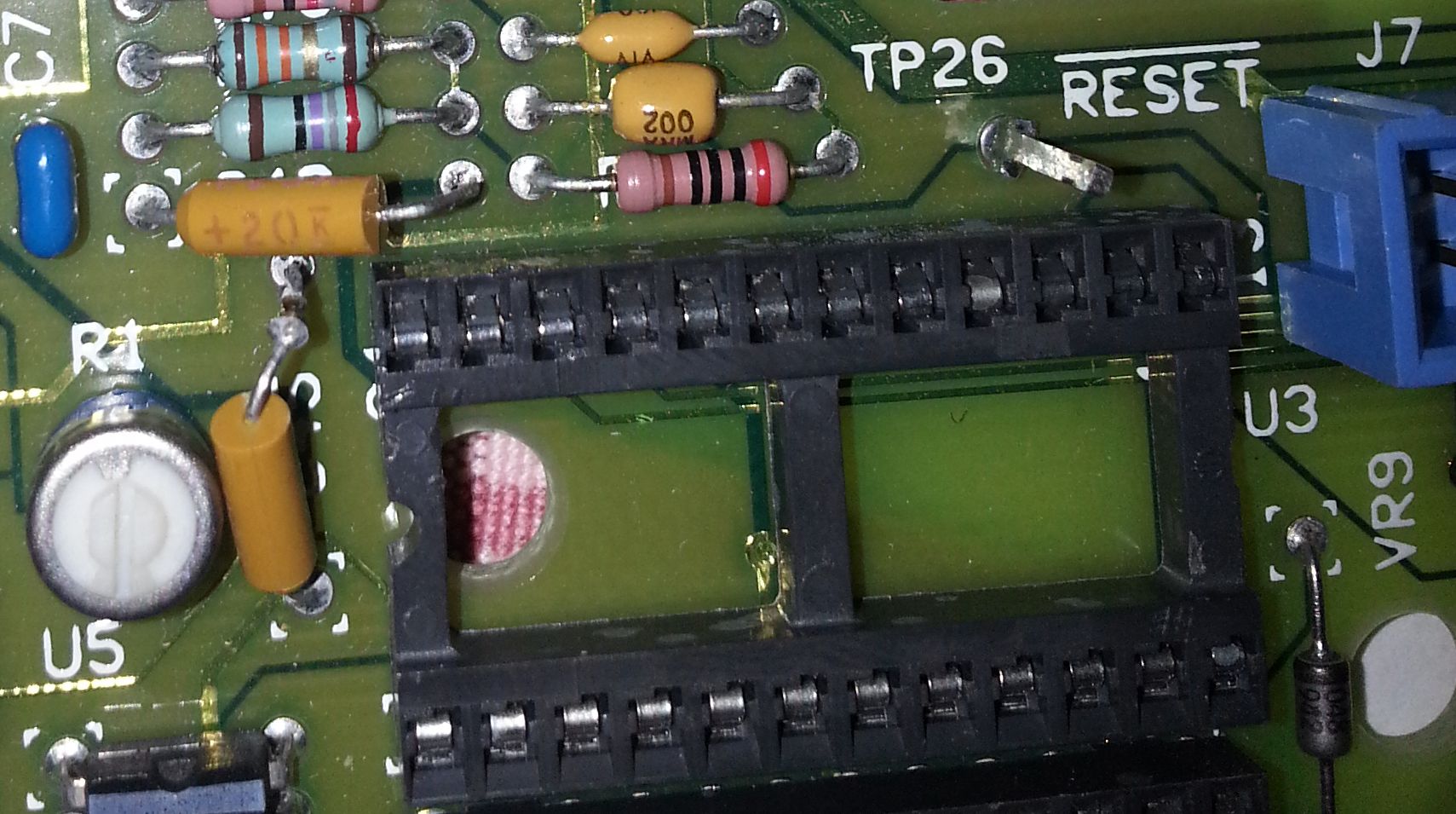
These 2 small (tantalum) caps near U3 were short. Not sure why they died when I powered the display unit with my power supplies, maybe I set them to a bit higher voltage then what the HP3562A generates.
I replaced them with the closer spare I found (4.7µF tantalum caps), and the Display Unit was up and running again.
I knows these old tantalum caps are prone to fail, and I should probably change them all, but I don't have enough spare for now.
After that, I could resume my adjustement procedure. And indeed there is an adjustment that allowed me to improve noticebly the brightness of the screen (the Intensity Cut-Off Level). Now I can run my HP3562A without the intensity knob FCW.
Brief description