One of my old test gears waiting for my attention in the cellar was a HP 3562A Dynamic Signal Analyzer. Back then I bought this device mainly for doing audio analysis (I was building my HiFi system, mostly based on Nelson Pass' schematics), mainly to display spectrum responses and compute THD and so.
I did not reall know what this test equipment is capable of. But Dave Jones's video #528 (and several wonderful videos on w2aew's channel) gave me the desire of playing a bit more with this old but very impressive HP3562A.
Quick tour
Here is the beast:
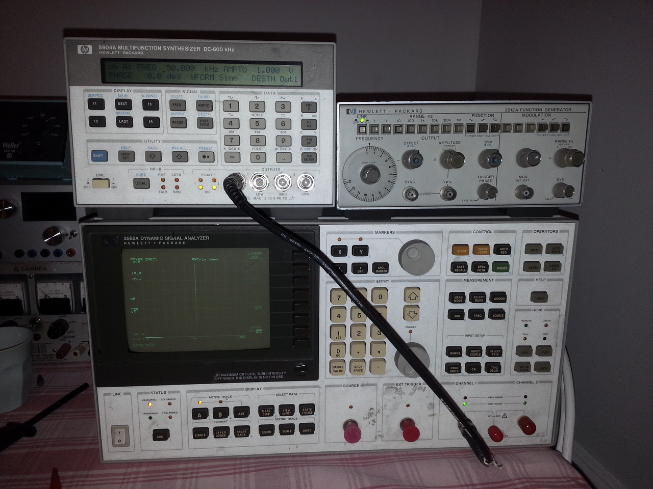
I said the beast, because despite being an amazing piece of test equipment, it's also very big (576mm x 426mm x 222mm), very heavy (26kg) and... unfortunately quite loud.
My version of the instrument is rather "recent", and manuals available on Keysight web site concern only the earliest models (ref. 03563-90210) and are of poor quality, with missing pages etc. So I bought the correct Service Manual (HP ref. 03562-90213) on ebay from Artek Media.
Since it was on my "bench", I decided to see a bit inside, using the occasion to investigate and fix the only real problem I have (as far as I know) with my device: the dimm display.
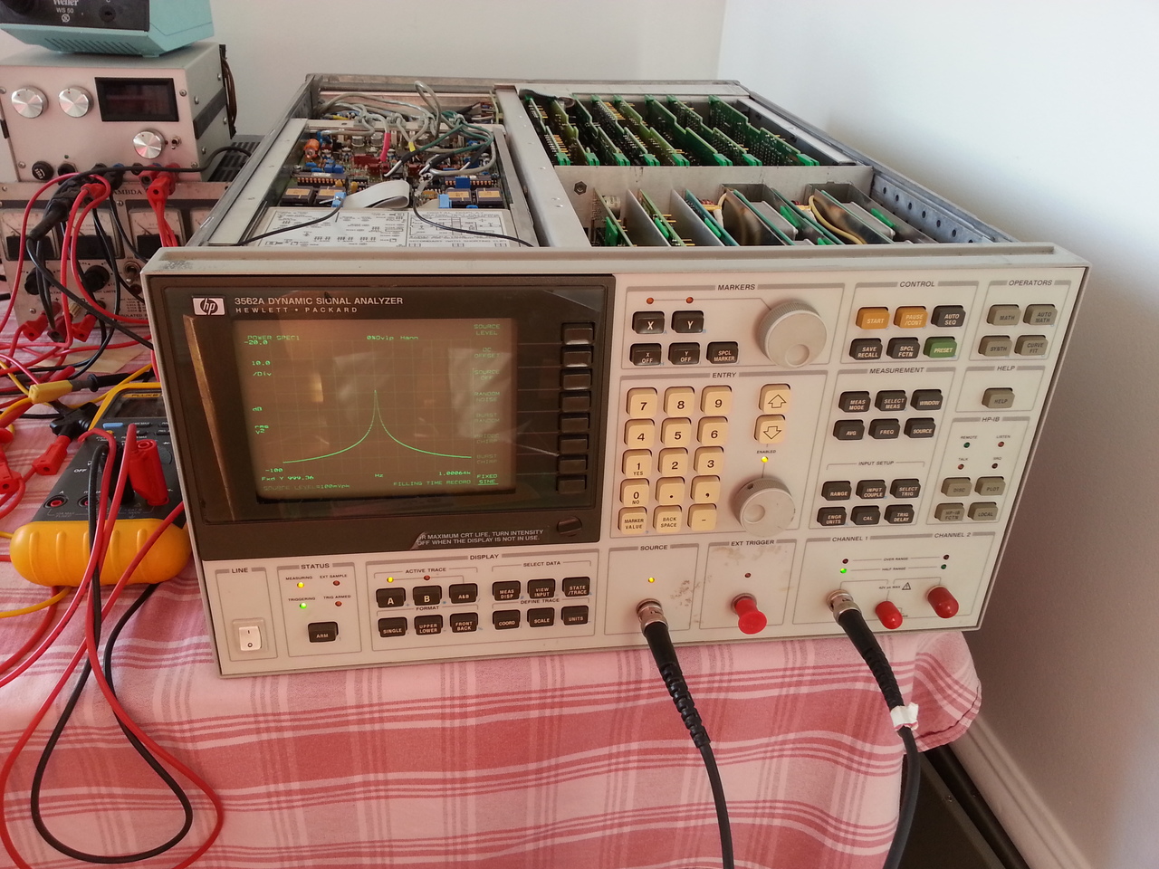
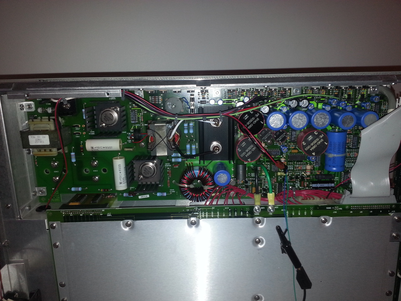
The unit consist in mostly 4 parts:
- a big switching power supply (with huge capacitors) on the left side of the enclosure, under the display,
- the display unit: a very nice HP1435A Digital Display; we'll discuss it a bit more later,
- the digital section consisting in 8 boards (rear right),
- the analog section consisting in 6 boards (front right).
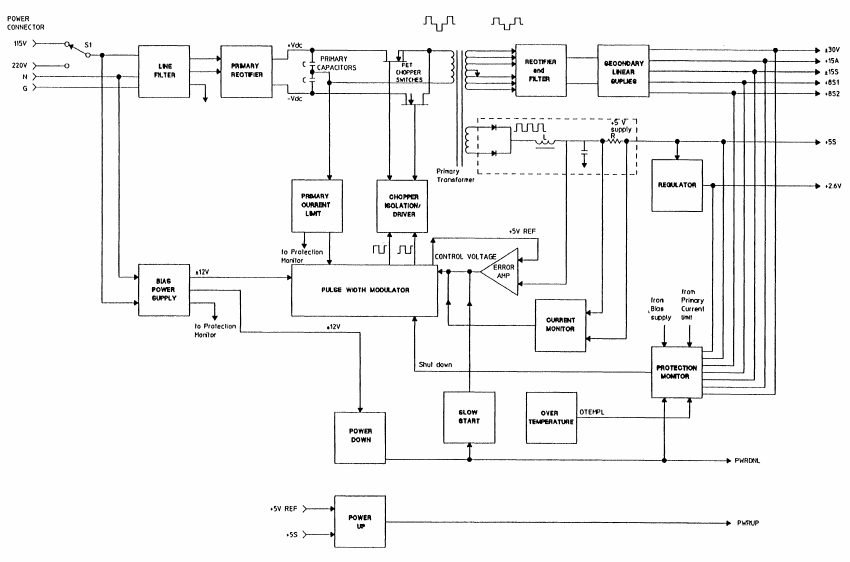
The general block diagram:
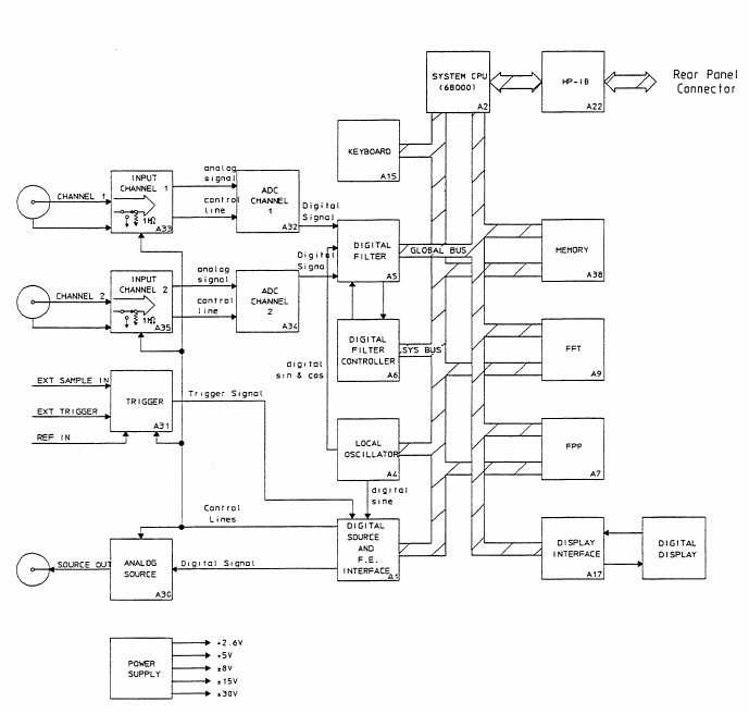
The instrument is built around 2 buses:
- the control bus which allows the main CPU to control all the assemblies, and
- the global bus which is used to transfer measurement data between assemblies.
In the HP3562A, the process control is distributed away from the system CPU: each assembly has its own processor or state machine which controls its local operations. The main CPU tells each assembly which process to execute and monitors the overall functionning and data processing of the instrument.
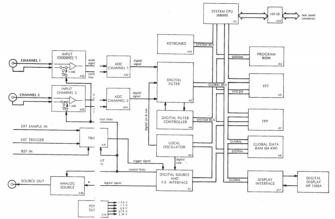
For the record, the block diagram from Service Manual 03562-90219 looks like:
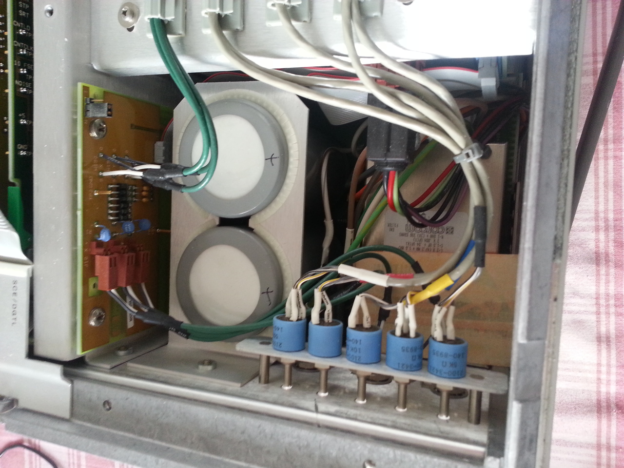
Power Supply
The primary capacitors are huge Sprague caps (1400µF 250V):
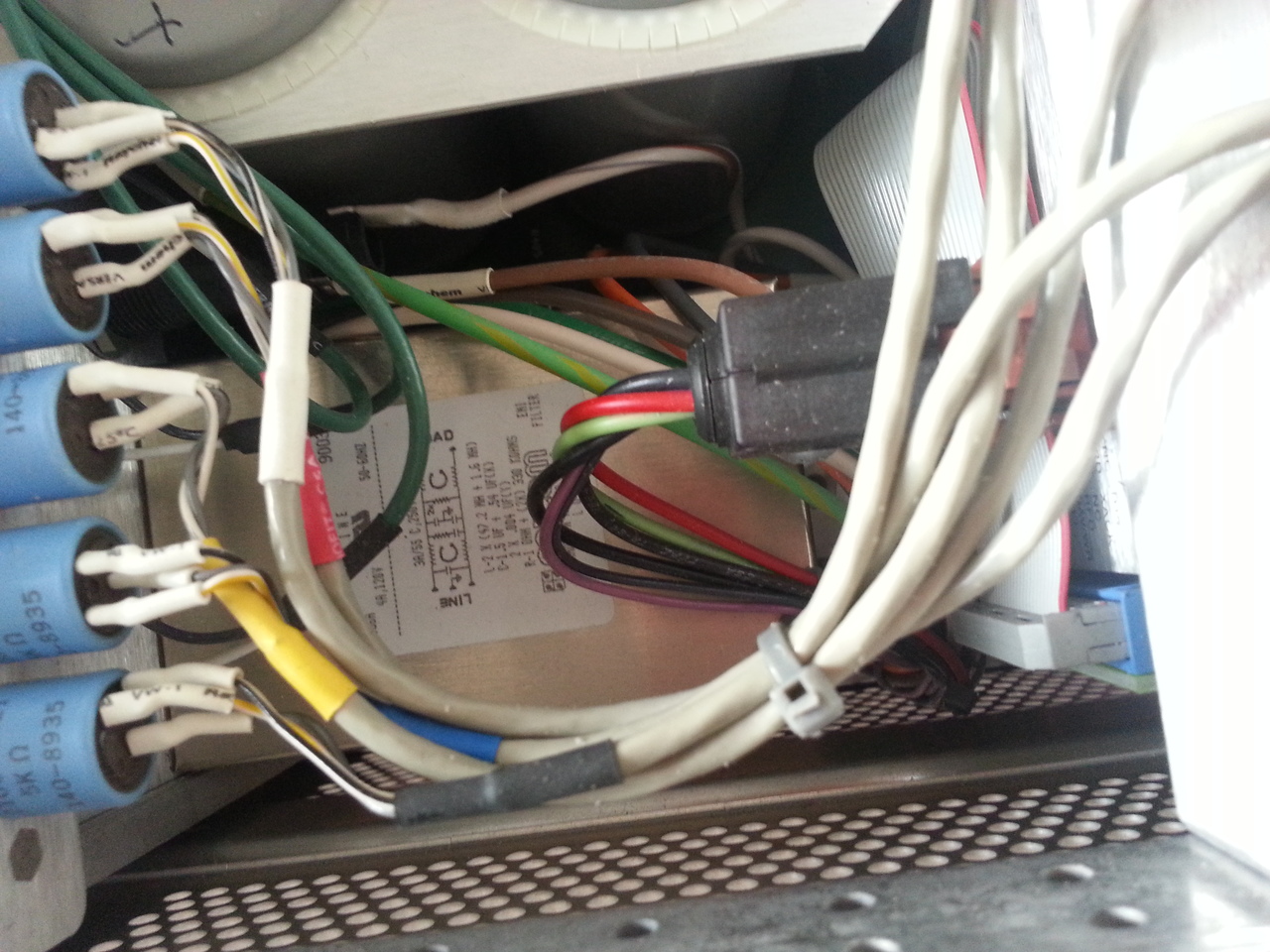
The power line filter is also pretty impressive:
The PSU generates:
- 5V @30A (!)
- +/- 30V
- +/- 15V
- +8V
- +2.6V
The switching chopper runs at 128kHz and is regulted on the 5V output rail by PWM of the primary transformer. All secondary voltages but the 5V are generated by linear regulators.
Next
In the next part, we will describe the Digital Section of the instrument.