My daughter's Numworks N0110 graphing calculator got fried when plugged in a cheap USB PSU. Black screen, heating up killing the battery in a matter of a few tens of minutes.
The design being originally Open Source (hardware and firmware), it makes sense to try to fix it instead of just buying a new one (it is not a cheap calculator).
The schematic is pretty simple: built around a STM32F730V8T6, there are only a few components surrounding the MCU:
- an LCD (280x320, 2,8", ST7789V driver) driven using the 16 bits 8080 interface, taking advantage of ST's FSMC controller,
- a 64MB flash (AT25SF641) to store apps and user data,
- LiPo charger (RT9526AGE),
- RT9078 2.8V voltage regulator to poser the MCU from the LiPo battery,
- LCD backlight DC-DC converter (RT9365GQW)
- 3 LEDs plus a number of passives, keypad, reset button,
- LiPo battery,
- USB port surge protection diodes (USBLC6-2SC6)
The list of fried devices was pretty much every active component:
- MCU,
- LCD,
- 2.8v regulator,
- USB protection diodes.
Due to the global chip shortage, I had to gamble on Aliexpress to find a STM32F730. I bought one from there. Against all odds, the delivered chip looks genuine and is working properly.
So I replaced the MCU and the 2.8v regulator. At this point, I wasn't sure about the status of the LCD. I did not know the USB protection diodes was dead, so uploading a firmware was quite a challenge; USB based DFU was not working (obvioulsy), but it was not obvious to understand why; I wasn't sure if a blank STM32 should enumerate ok as USB device, or if bootstrping a firmware was required before.
I also did not want to upload Numworks' latest official firmware nor using their WebDFU tools since they changes their licensing policy and moved to a closed source model, official firmwares since version 16.3 now lock the bootloader to prevent custom or open source firmware from being installed. A complete explanation of this (in French) is provided here
So I started looking at the alternative firmware projects for the Numworks: Omega, Phi, Khi and Upsilon (!) Plus starting from a blank STM32 instead of an upgrade from an existing installation added a bit of confusion.
After some time I got convinced I had successfully uploaded a firmware, but noting showed up on the LCD: diagnostic of a dead LCD as well...
The tricky part is that the LCD used in the calculator is pretty common on principle: standard size, usual LCD controller. The very one used in the calculator seems specificly made for the Numworks: specific ribbon cable and specific pinout. Could not find a compatible device on usual sources.
To validate I did indeed have a successfully replaced the MCU and uploaded a working firmware, I did a nasty rastnest experiment with a ST7789V LCD module I had around.
The result was pretty ugly
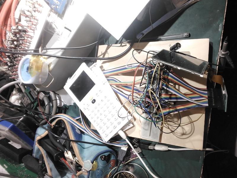
but I had some results:
First I was thinking the issue could be related to the speed of the communications between the MCU and the LCD: the signal path was far from optimal, with a ribbon cable, a breakout board, a bus of 10cm jump wires, a breadboard, another bunch of 10cl jump wires, yet another bunch of jump wires, another breakboard, and at last, the ribbon cable of the LCD module... So I spent some time hacking the Omega source code to reduce the transmission speed; but that did not help.
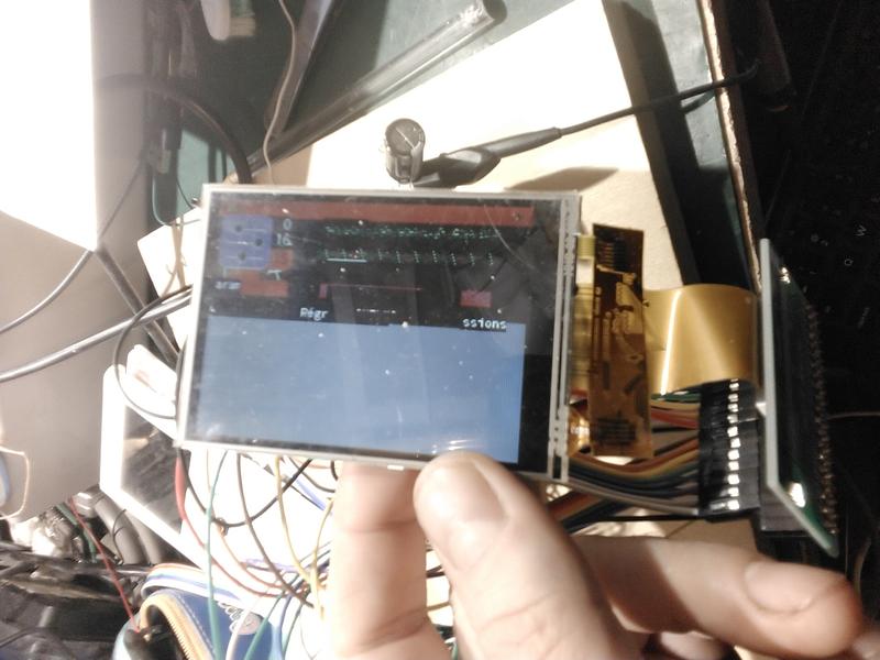
To figure out what was wrong I ended up using my DSLogic logic analyzer. The culprit was a pair of swapped jumpers (strangely there was only one pair of messed connections). Since it was a pair of data lines above D7, it was partially working. So the messed half display.
With the 2 wires back in order, result was much better...
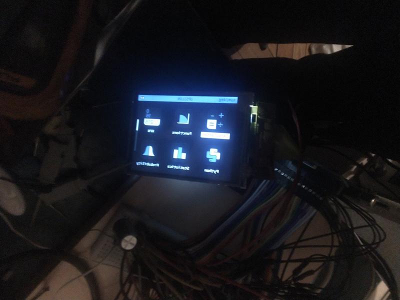
For some reason, this display showed the image reversed. Anyway, I was confident enough to spend a bit more money buying a replacemement LCD module.
Choosing a suitable replacement was not an easy task:
- It needs to use the ST7789V controller.
- It needs to be the proper size; seems easy, it's a standard 2.8" module... well no, most of these modules are 66.95x47.80mm while the module in the calculator is 66x50mm. Also the thickness must be about 2.1 or 2.2mm max.
- It needs to have the proper ST7789V signals available, 16bits 8080 mode; especially the Tearing Effect (TE) signal is used by the firmware to optimize display refresh timing.
- It needs to be an "12 o'clock" IPS LCD module (not a TN one) so the viewing angle is adapted when used in the calculator.
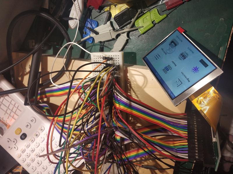
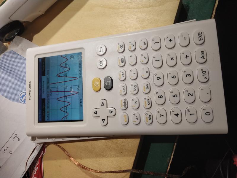
I found a few references on AliExpress (almost) matching all these contraints and bought this one.
Which worked nicely:
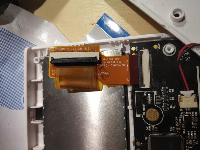
Obviously, the ribbon cable pinout is not the same as the original LCD module. So an adapter had to be made. At first I thought I could just solder a bunch of thin enameled wires, but this was not a very good idea; too hard to do properly, without damaging the ribbon cable etc. So I decided to try the new Flex PCB service JLCPCB (and others) now offer. Never did a Flex PCB design, was a nice opportunity to give it a try.
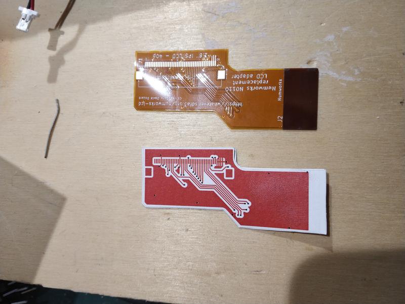
I did a simple design, with one side being connected to 30 pins FCP connector on the Numworks side, and the other side with a 40pins FCP connecter soldered onto the Flex PCB.
The design, printed on paper to check dimensions, looks like this:
The flex-PCB arrived a few days later:
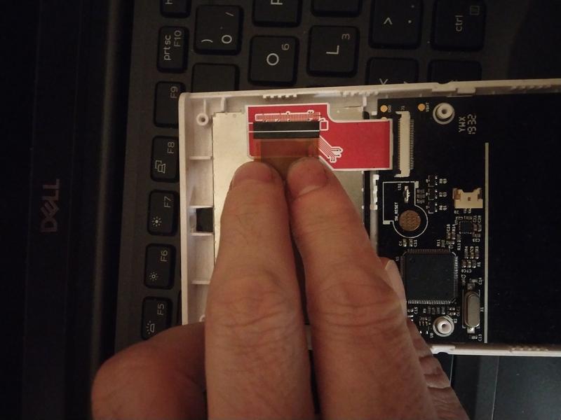
Was not sure how it would support hand soldering the FCP connector, but it went ok.
It fits pretty nicely in the Numworks enclosure; the only modification I had to make it to trim a bit some plastic pads to fit and center le LCD module.
The Kicad design for the Flex-PCB is available here.