I recently pulled an HP 8662A I bought a while ago from my cellar. I don't remember exactly in what condition it was advertized when I purchased it, but it was most probably advertized as non working (otherwise it would have been cheap enough, more, what the fun in buying properly working test equipment?)
I wanted to make a break in my current other repair project, the EIP 545B Microwave Fequency Meter, also having a properly working unit such as this incredible signal synthetizer would be quite useful to perform several adjustement tasks on the EIP 545B.
Carrying the unit from my cellar to my appartement was some kind of a job: it's a robust 30kg device I had to climb the 7 levels: no lift in the old parisian building I live in...
Overall state and disassembly
The unit was in reasonably good condition, but is missing a few parts: the feets, 2 of the plastic corners on the back, and the nice quick sliding guide normally located on the bottom. Buttons however were very hard for most of them but 2, which were very soft and sloppy.
I think I tried to power it up when I received it a couple of years ago, and that it did start, but the keybord did not respond smoothly.
So when I started to look at it two weeks ago, I opened the upper cover and the protection plate above the PSU, and tried to plug it and power it up. Obviously, a small magic smoke escaped.
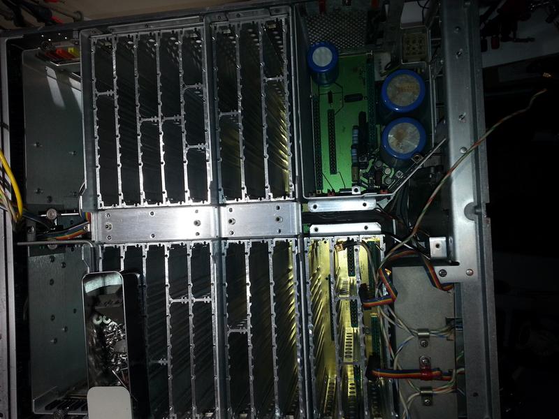
So I gave a more detailed look inside the unit, not only the PSU. I found the unit so dirty inside I decided to take it apart as far as I can to clean it before even attempting to fix the PSU.
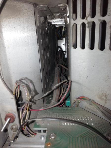
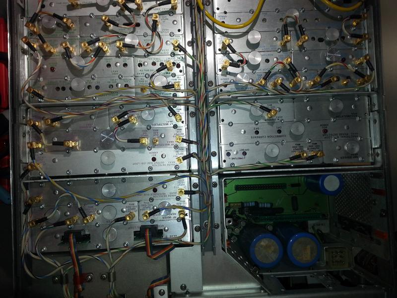
And I must say that if most of the unit is very easy to service due to the modular design of all RF modules, making is very easy to remove all the boards and modules, there are also many parts that are connected together with wires soldered point to point, which makes disassembling the case, motherboards and so very tedious.
Also, there are hundreds of screws in this unit! it's insane.
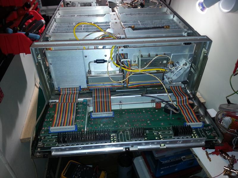
Whatever, I finally got to a point I could clean most of the parts of the unit, so I started to reassemble it. Unfortunately, I did not took enough pictures while the disassembling, so it took me some effort to have something that looks like an HP 8662A...
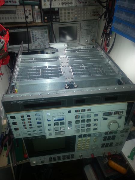
Once I had the structure of the generator back together, with the back plane in place but no other board nor module plugged in, I started to take care of the PSU.
The PSU
As I said, the first attempt to plug (and not even power on) the unit ended with a small magic smoke. The PSU consists in 2 main parts:
- A small linear power supply that is always powered to keep the OCXO tempearure regulation on all the time (so it's not necesary to wait an hour before being able to actually use the device when turned on), This also power a small part of the control circuit of the main PSU.
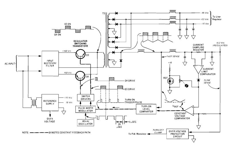
- The main switching power supply. The high voltage section is allways on, and the mani switch on the front panel only activate the switching.
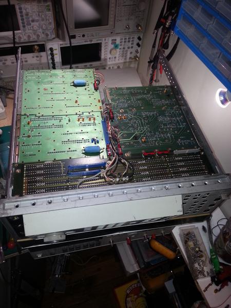
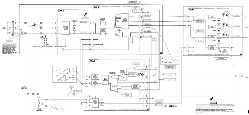
The 4 boards the PSU is made of are:
- a main board (A7A4) on which are the first stages of the AC rectification and filtering,
- a daugther board (A7A3) on which is the inverter, generating several unregulated voltages: +5.2V (used as control rail for the feedback loop), +23V, -13V and -43V; note that this board doaes not have the switching control circuitry,
- a daughter board (A7A1) with the linear regulators to produce very clean and quiet power rails for the RF modules; its output voltages are +20V (+/-100mV), -10V (/- 40mV) and -40V (+/-200mV),
- a daughter board (A7A2) with the switching control circuit. The switching regulation being made on the 5.2V rail, which is not regulated by A7A1.
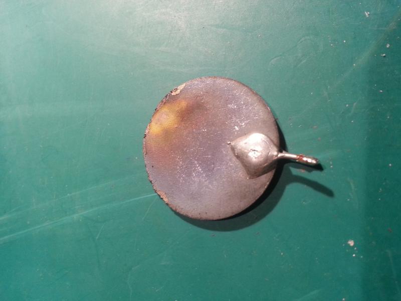
So I gave a close look at thes boards, beginning by the main board, the I found the culprit for the smoke: the input protection thermistor. Strangely, it still measures a decent resistance value, but hey.
The thermistor is described the old fashion way: it's a 5Ω @25°C with a temperature coefficient of -3.8%/°C. I did not find an exact replacement in my junk parts; only a slighty highter value one (a XXX, which is more like 20Ω @25°C). Not ideal, but for now, it seems to work fine.
After this first step forward, I was not confident enought to plug the boards back in place and try again (I am always worried when I repair switching PSUs... they can fail in flame and glory sometimes). So I checked all the diodes and transistors of the PSU, but none looked short.
I first applied power to the main board: nothing exploded, I was now having a nice + and -160VDC and the oven power was on spec.
Next step, I checked transformers of the inverter board before plugging it back, still no catastrophic failure. The inverter alone cannot do anything without the control board.
So I quickly checked the 2 other board before plugging them back. So far so good.
But when I tried to turn power on, the voltege OK green LEDs flickered once but did not stay on, and the error LED did turn on. All the voltages produced by the inverter board were very low. Somethin was wrong.
Looking at the schematics and the boards, I did find several failure points:
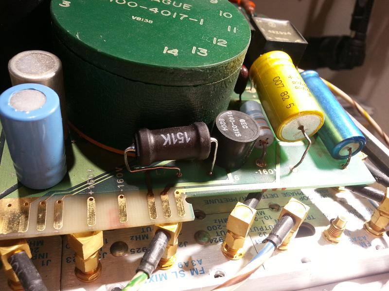
one of the 2 150µH inductors on the 160VDC rails (L6 anf L7 on A7A3) ) looked a bit odd to me: it was not sitting flat on the PCB, which it should for this kind of inductor; and when I gently tried to wiggle it, it appeared a leg was broken, unfortunately too short to be able to solder a piece of wire, so I replaced it with a brand new inductor I recently bought when I repaired an old analog scope (Metrix OX734) for a friend of mine (I allways buy several more parts than I really need, when these are cheap, just in case; seems to be a good idea),
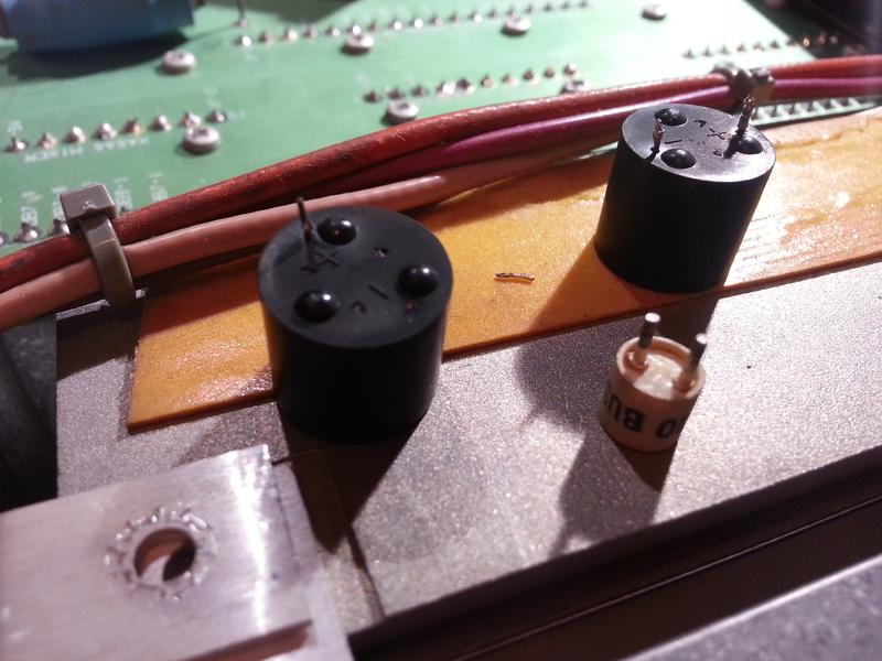
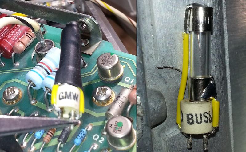
there are 2 small 400mA fuses on the inverter board to protect the base of the 2 switching (bipolar!) transistors (first time I see the base of an NPN transistor protected by a fuse, but it's also the first time I repair a switching PSU which the main switching transistors are bipolar ones and not MOSFET or so). These are small BUSS GMW 4/10 (400mA) fuses, they look nice and so but are very expensive (and a bit hard to find): something like 15€ each. So for now, I've replaced it with a simple 5x20 glass fuse: not as skookum but does the job for a few cents.
After these fixes, I reassembled the PSU and tried again: the result was quite promising, but not a complete success: the PSU seemed to start, but very quickly stops itself with an error LED on: the overvoltage protection was shuting down the power.
I tried to check several things on the error detection circuits with no succes, and when (at last) I began to follow the service manual instructions, I found this paragraph about this overvoltage error:
If red LED in the upper left hand corner of the board is lit indicating the input voltagr from the A7A3 Inverter assembly was too high and the supply was shut down, it is most likely a problem with the regulator not drawing enough current.
Just had to plug back enough boards and modules for the PSU to be happy again!