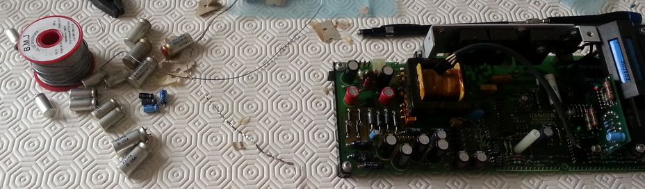
After a quick repair of the PSU of my Tek 2445, I've started a more systematic replacement of the capacitors.
But I was also a bit worried because of a dirty noise coming from the preregulator area.
After having replaced most of the electrolytic capacitors, the dirty noise became louder (I think. It might be unrelated, not sure yet). The PSU became very untrusty: a small plume of smoke began to escape from somewhere (could not identify precisely where exactly). I started probing around, but at this moment, I had no idea which component was getting too hot: I always shut the power off after a few seconds of power, with the T1050 transformer singing as soon as the preregulator control oscillator starts up (U1030).
During this probing and checking period, I discovered that the CR1040 diode from the current limitation circuit was dead (short)... Unfortunately, it's a germanium diode (used for it's low voltage drop, about 0.2v). Fortunately I found one of them which should fit in my very old spare components casket (the one I had when I was a kid).
Then, in order to try to see things, I started to power the PSU up for a few seconds (sometimes maybe tens of seconds) trying to probe (without my scope, obviously, so only with my Fluke 867B which allows me to see some kind of signals.)
Which allowed me to finally find the culprit for the smoke: R1071 (in red on the schematic below). Its value is still fine, but it's getting very hot as soon as the main oscillator starts up. A bit strange, since the capacitor C1071 seems fine (I do not have a ESR meter, but hey, there is no way higher ESR could lead to overcurrent flowing through this resistor).
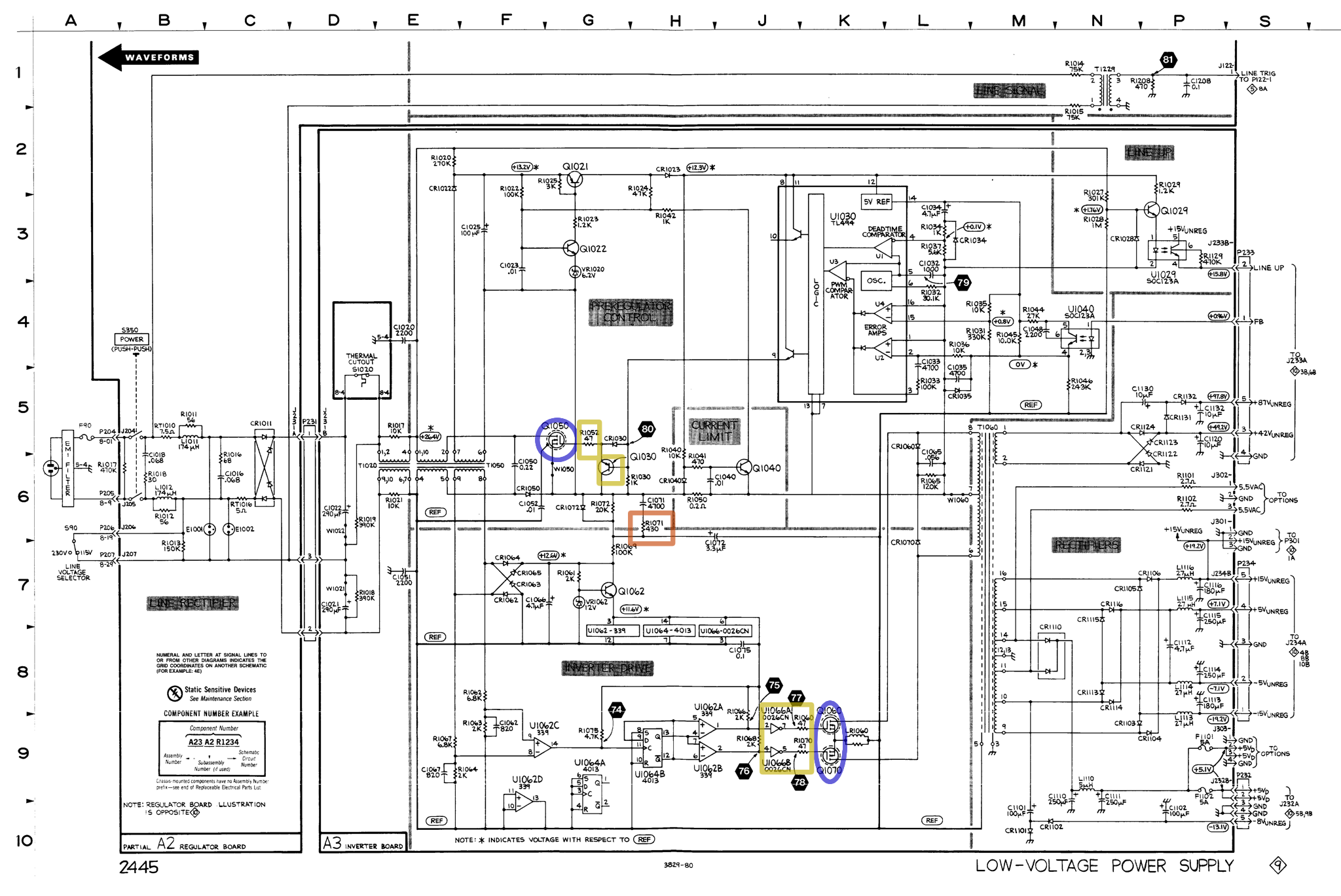
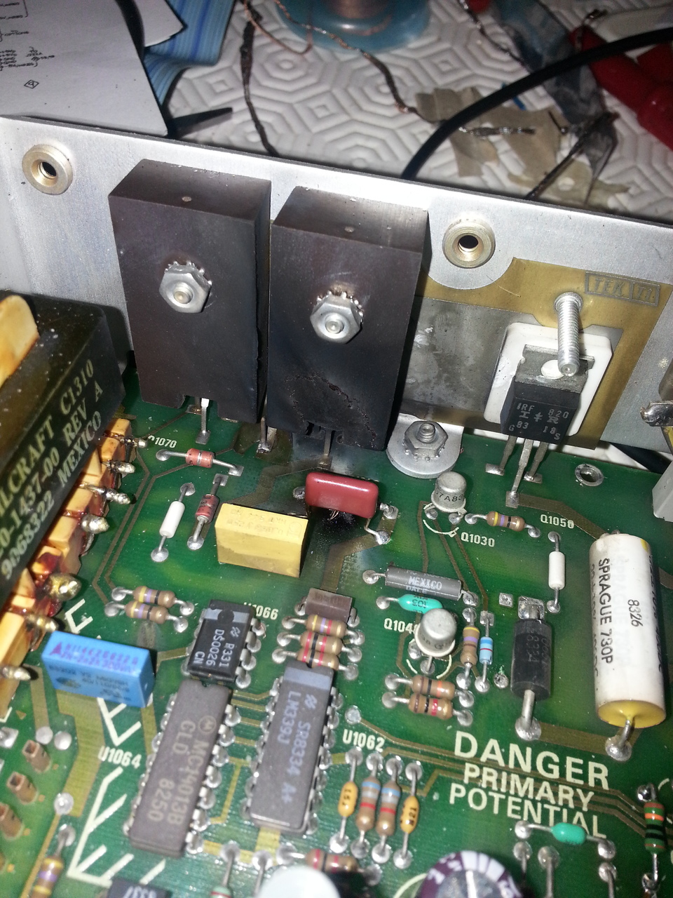
But powering up and down the PSU again and again, with its freaking and noisy switching problem, finally killed the MOSFET (IRF820) power transistors (Q1050, Q1060 and Q1070) producing flames. The plastic protection on Q1060 directed all the heat directly on the poor LR1060 which exploded as well... Which is a problem since I do not know the exact specifications of the device; the service manual do not give the value of the resistor in parallel with the 2.5µH inductance.
For now, I've picked up a 3W 100Ω resistor and I've made a self by hand. As I don't have a RLC meter, I don't known its exact value so I've took a few measures of its impedance at several frequencies, and I estimate the inductance to be around 4 µH. I have no idea whether this higher value might be a problem... But I've no idea either if the 100Ω resistor I've used as core for the coil is fine or not.
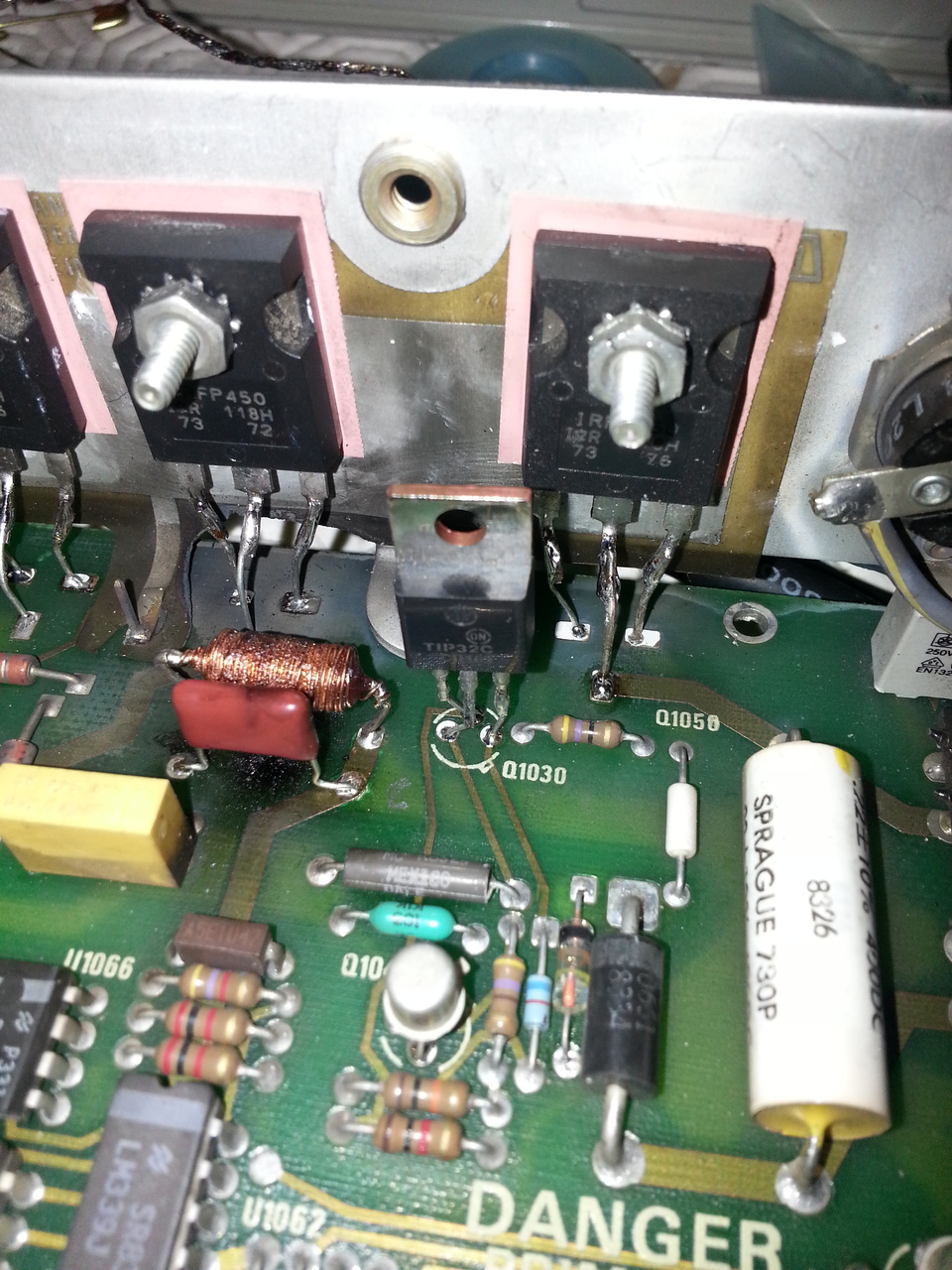
And I have other problems to fix. First, the 3 MOSFETs have to be replaced... As I don't have anything near IRP820 in my hood, I've picked up some IRFP450 I extracted from computer PSUs. These are much bigger than the IRF820, but having beafier models (with higher max current and voltage) should not be a problem there. The only thing that worries me a bit is the much lower Rds value (0.4Ω versus 3Ω for the IRF820). Means higher peak currents. Q1030 and R1052 also died. The transistor is a 2N3905 (which I don't have around either) so I've replaced it with a bigger TIP32C.
From there, I began to check most of the components in this preregulator part of the PSU before even attempting to apply power.
I've checked the behavior of the main control oscillator (made of U1030), by powering it with my new old Lambda linear power supply. Applying power at the leads of C1025, I could also check the behavior of the Q1020/Q1021 stage. Their purpose is to regulate the supply voltage for the U1030 main oscillator.
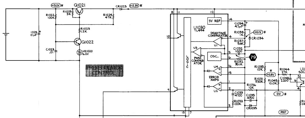
At power-up time, when the oscillator has not yet started, R1020 fill C1025 from the input high voltage DC. When the voltage on C1025 reaches about 21V, Q1021 is activated, powering U1030 (from C1025), and doing so, putting R1024 in parallel with R1020, making the voltage required to keep Q1021 saturated much lower (around 8V theorically).
With the energy stored in C1025, U1030 can start oscillating, starting effecively the preregulated power supply, which make switching current flow through T1050, from which the coil at leads 6 and 7 should now provide something like the 15V used to power the main preregulator oscillator. So far so good. On my PSU, this main oscillator seems to work fine even if I've found that the voltages at which thing happen are significantly smaller than the values above (which come from the service manual). It's more like:
- 18V for Q1021 to be saturated (instead of 21V),
- 7V for Q1021 to be blocked again (instead of 8V).
Not sure whether I should care about this. Probably not.
The other part of the preregulator is the inverter drive. Its purpose is to switch the current flowing in the T1060 transformer (the output of the preregulator part) from one direction to the other in its primary circuit at each pulse of the switching in T1050.
With Q1060 and Q1070 being dead, I was expecting a few more components around to have suffer. And some more dead puppies there were: R1060 and R1070 have died also (open) and, more annoying, U1066. It's a bit more annoying since this chip is a DS0026CN, which is obsolete and cannot be found at DigiKey or Mouser any more.
Thanksfully, it's still available on ebay. So I've bough a pair of them, and that's where I am now in this epic attempt to repair this poor PSU.
I've also bought a Rigol DS1054Z (waiting for it to be delivered also), I hope it will help me figure what's really going wrong in this preregulator stage. Obviously there is something not working properly, probably a high frequency signal in the switching. The creepy noise in T1050 and R1071 beginning to burn are clear signs of this high frequency noise, probably inducing high voltage spikes or some stuff like that.
A few things I've noticed that seems rather strange to me:
- R1069 is marked as 100kΩ on the service manual, it was 33kΩ on mine,
- the schematic indicate a +264V at the output of the T1020 choke, but I don't understand how such a low value is possible (with a 240VAC input voltage, I expect this value to be around 330V, which is the value I measured IIRC),
- voltage values indicated on the schematic in the service manual with a * sign should be with respect to REF signal. But I don't see how the voltage at the terminals of U1030 can be given relative to REF. I read (and measured) these values realted to the GND pins of U1030, which is the switched +264V (or +330V in my case) high voltage at the middle terminal of the primary coil of the output transformer.
While waiting for my DS0026 spare ICs, I'm trying to figure how I can elaborate a setup in which I am able to test the PSU without risking its life again. I'll have to find my variac in my cellar, I guess.