After having mostly destroyed the PSU of my Tek 2445, I've decided to be a bit less foolhardy and I've subscribed to the yahoo Tek group. I discovered that such a failure has already been reported there, also after a full recap of the preregulator and regulator of the power supply.
I also found that I was not completely wrong when I built my replacement LR1060.
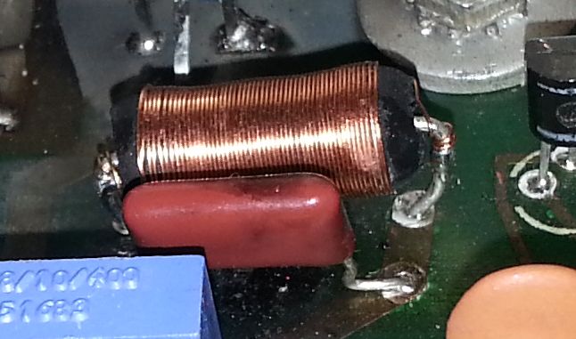
It seems to be built on a 75Ω resistor. Mine was not so far, but I decided to rebuild one with closer specifications, so I took a new 68Ω resistor and I wrapped some 34 gauge wire around. The result is a bit cleaner, from:
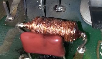
to:
However, I was stuck because of my dead T1050. Due to the lack of success getting the main oscillator starts, I end up suspecting that T1050 had suffered when Q1050 exploded... And I was right: one of the two primary coils was short.
I've found a reasonnably cheap replacement part on QService Electronics shop. It took a bit long to arrive (12 days from Greece to France, but to be honest, it seems the longest part of the transit was in France), but it arrived. So yesterday evening I've been able to replce it.
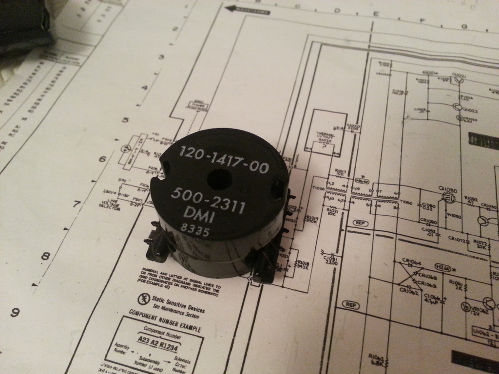
The T1050 transformer
This transformer is a small input transformer with 4 coils around a common ferrite core:
I was not sure of the specifications of each coil, since mine as (at least on one coil) defective. From the schematic, it looked natural that both the primary windings should have the same charactritics. So when my replacement transformer arrived, I took a few measurements.
The result is:
| Winding | R | L |
|---|---|---|
| 1-2 | 4Ω | 6mH |
| 4-5 | 4.5Ω | 6.5mH |
| 6-7 | 0Ω85 | ~ 10µH |
| 8-9 | 0Ω8 | ~ 10µH |
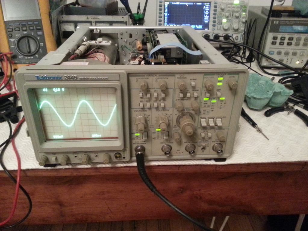
I've also quickly checked the voltage ratios using a 42kHz signal:
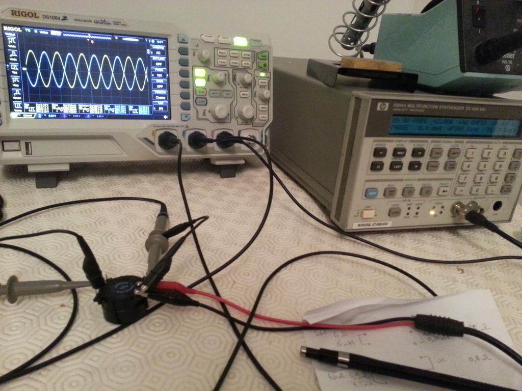
I use CH2 of my scope to probe the signal produced by the HP890A4 linked to pins 1 and 2 (thus a primary winding), and CH1 on a secondary winding (pins 6-7), which resulted in:
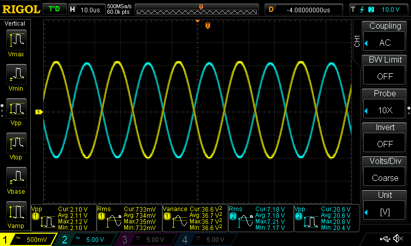
As one can see, the turn ratio seems to be 10. Both the 2 secondary windings (6-7 and 8-9) which provide power for the preregulator control (U1030) and the inverter drive (U1062, U1064 and U1066), are identical to each other.
Testing the new T1050 transformer
After having soldered the "new" T1050 transformer, I followed one part of the Power Supply Troubleshooting Procedure from the Service Manual. In the diagram, there is a path in which there is:
Unsolder and lift the end of W1060 near pin 7 of T1060;
Connect the primary test load between the lifted end of W1060 and the sources of Q1060 and Q1070;
Power up and check for 120V accross load (plus a 1Vpp triangle wave).
The test load consist in:
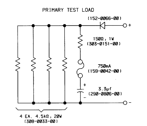
So I built one and connected it:
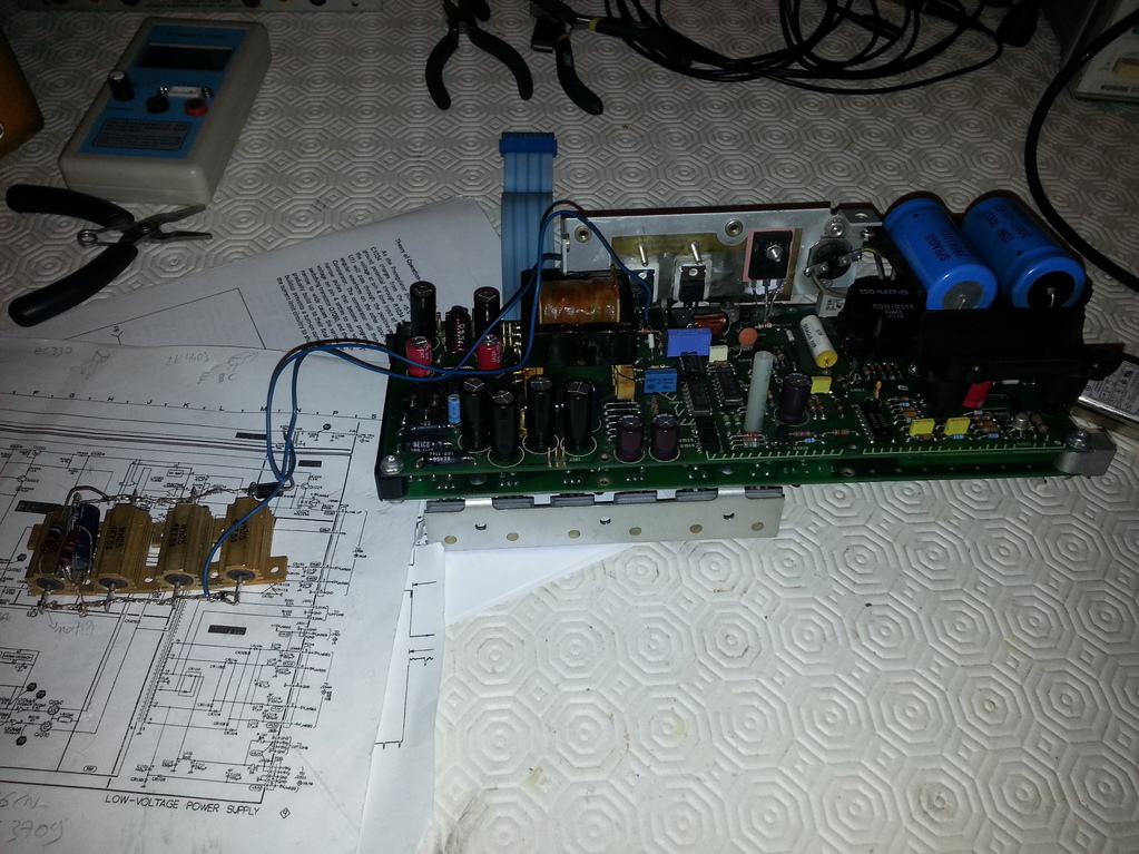
Was a little anxious when I switch the PSU on, but it did not exploded. And the voltage across the dummy load was just fine!
So I resoldered W1060, reinserted all the jumpers (between A2 and A3), plugged in a dummy load on J303 (unregulated 5V), a tried again. The PSU was starting... it was not completely stable though, but I was pretty sure this was due to the fact the load was not correct. So I reinstalled the PSU in the scope, and gave it a try:
At last!
Summary
I've spent a lot of time trying to understand and fix this PSU. I think I've lost a lot of time and effort because I've been too hasty, and I should have taken more time reading the service manuals. By the way, the service manual for the Tek 2465A is a better source of documentation, for example the question I had about the voltages with respect to "REF" on the schematic is answered in this later manual: there are indeed 2 references, as I suspected.
The main lesson from this is: never test a switching power supply unloaded. I'm pretty sure I blew up the power transistors, the transformer and a few other parts because I was switching the unloaded PSU on and off. It's probably a lesson 101 on switching power supplies... never too late to learn.
A the end, I've replaced many parts on my A3 preregulator board. Some are probably not required:
- T1050,
- Q1060 and Q1070: I replaced with IRF820,
- Q1050: replaced with a IRFP450;the higher gate capacitance seems not to be problematic finally,
- Q1022, Q1030, Q1040 and Q1063: replaced with 2N4403 and BC337 (the transistors I found at my local components store)
- almost every capacitor,
- U1029 and U1040 optocoupler ,
- U1066: replaced by a DS0026CN bought on ebay
- CR1040: replaced by an unknown germanium "similar looking" diode,
- R1060 and R1070,
- R1069
So I'm done for now with this puppy. It should be completely checked, but that will be another story.
Post Scriptum
For the fun:
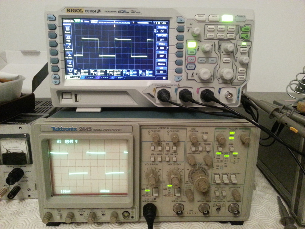
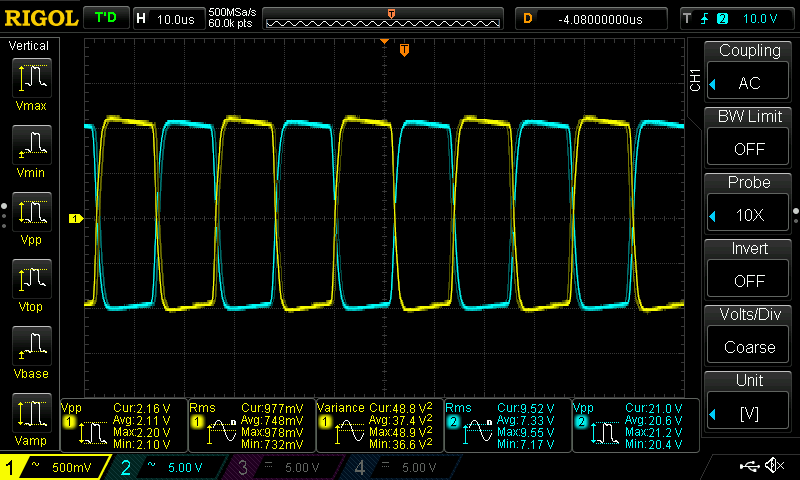
Despite the fact the Rigol DS1054Z has an incredible number of features for which the Tek cannot compete, I still like this old puppy a lot. Its front panel is much easier to use: every control is directly accessible. And yet, I don't think the Rigol can measure both the rise and fall time (with a decent precision) of a square wave:
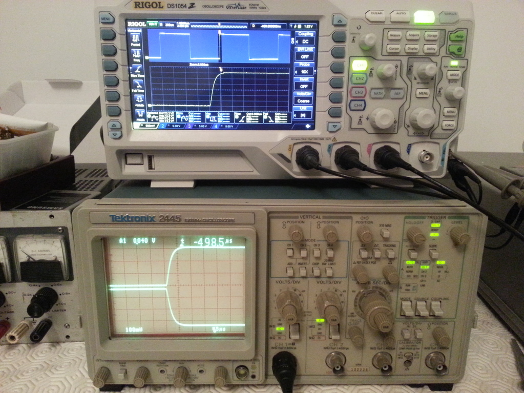
Beautiful double time-base!